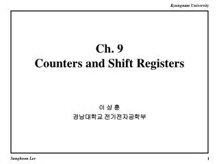
Behavioral Design Style: Registers, Counters, Shift Registers Basic Testbenches
ECE 448 Lecture 5. Behavioral Design Style: Registers, Counters, Shift Registers Basic Testbenches . Required reading. S. Brown and Z. Vranesic , Fundamentals of Digital Logic with VHDL Design Chapter 7, Flip-Flops, Registers, Counters, and a Simple Processor

Behavioral Design Style: Registers, Counters, Shift Registers Basic Testbenches
E N D
Presentation Transcript
ECE 448 Lecture 5 Behavioral Design Style:Registers, Counters, Shift RegistersBasic Testbenches ECE 448 – FPGA and ASIC Design with VHDL
Required reading • S. Brown and Z. Vranesic,Fundamentals of Digital Logic with VHDL Design • Chapter 7, Flip-Flops, Registers, Counters, • and a Simple Processor • (7.14 optional) ECE 448 – FPGA and ASIC Design with VHDL
Optional Reading • Sundar Rajan, Essential VHDL: RTL Synthesis • Done Right • Chapter 4, Registers and Latches • Chapter 5, Counters and Simple Arithmetic • Functions • (see errata at http://www.vahana.com/bugs.htm) ECE 448 – FPGA and ASIC Design with VHDL
Behavioral Design Style: Registers & Counters ECE 448 – FPGA and ASIC Design with VHDL
What is a PROCESS? • A process is a sequence of instructions referred to as sequential statements. The keyword PROCESS • A process can be given a unique name using an optional LABEL • This is followed by the keyword PROCESS • The keyword BEGIN is used to indicate the start of the process • All statements within the process are executed SEQUENTIALLY. Hence, the order of statements is important. • A process must end with the keywords END PROCESS. testing: PROCESS BEGIN test_vector<=“00”; WAIT FOR 10 ns; test_vector<=“01”; WAIT FOR 10 ns; test_vector<=“10”; WAIT FOR 10 ns; test_vector<=“11”; WAIT FOR 10 ns; END PROCESS; ECE 448 – FPGA and ASIC Design with VHDL
Anatomy of a Process OPTIONAL [label:]PROCESS[(sensitivity list)] [declaration part] BEGIN statement part ENDPROCESS [label]; ECE 448 – FPGA and ASIC Design with VHDL
Statement Part • Contains Sequential Statements to be Executed Each Time the Process Is Activated • Analogous to Conventional Programming Languages ECE 448 – FPGA and ASIC Design with VHDL
List of signals to which the process is sensitive. Whenever there is an event on any of the signals in the sensitivity list, the process fires. Every time the process fires, it will run in its entirety. WAIT statements are NOT ALLOWED in a processes with SENSITIVITY LIST. label: process (sensitivity list) declaration part begin statement part end process; PROCESS with a SENSITIVITY LIST ECE 448 – FPGA and ASIC Design with VHDL
Processes in VHDL • Processes Describe Sequential Behavior • Processes in VHDL Are Very Powerful Statements • Allow to define an arbitrary behavior that may be difficult to represent by a real circuit • Not every process can be synthesized • Use Processes with Caution in the Code to Be Synthesized • Use Processes Freely in Testbenches ECE 448 – FPGA and ASIC Design with VHDL
Use of Processes in the Synthesizable Code ECE 448 – FPGA and ASIC Design with VHDL
All signals which appear on the left of signal assignment statement (<=) are outputs e.g. y, z All signals which appear on the right of signal assignment statement (<=) or in logic expressions are inputse.g. w, a, b, c All signals which appear in the sensitivity list are inputs e.g. clk Note that not all inputs need to be included in the sensitivity list Component Equivalent of a Process clk y w priority a z b c priority: PROCESS (clk) BEGIN IF w(3) = '1' THEN y <= "11" ; ELSIF w(2) = '1' THEN y <= "10" ; ELSIF w(1) = c THEN y <= a and b; ELSE z <= "00" ; END IF ; END PROCESS ; ECE 448 – FPGA and ASIC Design with VHDL
VHDL Design Styles dataflow VHDL Design Styles structural behavioral Concurrent statements Components and interconnects Sequential statements Registers & counters ECE 448 – FPGA and ASIC Design with VHDL
Registers ECE 448 – FPGA and ASIC Design with VHDL
Q D Clock D latch Truth table Graphical symbol Q(t+1) Clock D Q(t) – 0 0 1 0 1 1 1 Timing diagram t t t t 1 2 3 4 Clock D Q Time ECE 448 – FPGA and ASIC Design with VHDL
Q D Clock D flip-flop Truth table Graphical symbol Q(t+1) Clk D 0 0 1 1 – Q(t) 0 Q(t) 1 – Timing diagram t t t t 1 2 3 4 Clock D Q Time ECE 448 – FPGA and ASIC Design with VHDL
Q D Clock D latch LIBRARY ieee ; USE ieee.std_logic_1164.all ; ENTITY latch IS PORT ( D, Clock : IN STD_LOGIC ; Q : OUT STD_LOGIC) ; END latch ; ARCHITECTURE Behavior OF latch IS BEGIN PROCESS ( D, Clock ) BEGIN IF Clock = '1' THEN Q <= D ; END IF ; END PROCESS ; END Behavior; ECE 448 – FPGA and ASIC Design with VHDL
D flip-flop LIBRARY ieee ; USE ieee.std_logic_1164.all ; ENTITY flipflop IS PORT ( D, Clock : IN STD_LOGIC ; Q : OUT STD_LOGIC) ; END flipflop ; ARCHITECTURE Behavior_1 OF flipflop IS BEGIN PROCESS ( Clock ) BEGIN IF Clock'EVENT AND Clock = '1' THEN Q <= D ; END IF ; END PROCESS ; END Behavior_1 ; Q D Clock ECE 448 – FPGA and ASIC Design with VHDL
D flip-flop LIBRARY ieee ; USE ieee.std_logic_1164.all ; ENTITY flipflop IS PORT ( D, Clock : IN STD_LOGIC ; Q : OUT STD_LOGIC) ; END flipflop ; ARCHITECTURE Behavior_2 OF flipflop IS BEGIN PROCESS BEGIN WAIT UNTIL Clock'EVENT AND Clock = '1' ; Q <= D ; END PROCESS ; END Behavior_2 ; Q D Clock ECE 448 – FPGA and ASIC Design with VHDL
D flip-flop with asynchronous reset LIBRARY ieee ; USE ieee.std_logic_1164.all ; ENTITY flipflop IS PORT ( D, Resetn, Clock : IN STD_LOGIC ; Q : OUT STD_LOGIC) ; END flipflop ; ARCHITECTURE Behavior OF flipflop IS BEGIN PROCESS ( Resetn, Clock ) BEGIN IF Resetn = '0' THEN Q <= '0' ; ELSIF Clock'EVENT AND Clock = '1' THEN Q <= D ; END IF ; END PROCESS ; END Behavior ; Q D Clock Resetn ECE 448 – FPGA and ASIC Design with VHDL
D flip-flop with synchronous reset LIBRARY ieee ; USE ieee.std_logic_1164.all ; ENTITY flipflop IS PORT ( D, Resetn, Clock : IN STD_LOGIC ; Q : OUT STD_LOGIC) ; END flipflop ; ARCHITECTURE Behavior OF flipflop IS BEGIN PROCESS BEGIN WAIT UNTIL Clock'EVENT AND Clock = '1' ; IF Resetn = '0' THEN Q <= '0' ; ELSE Q <= D ; END IF ; END PROCESS ; END Behavior ; Q D Clock Resetn ECE 448 – FPGA and ASIC Design with VHDL
8 8 Resetn D Q Clock reg8 8-bit register with asynchronous reset LIBRARY ieee ; USE ieee.std_logic_1164.all ; ENTITY reg8 IS PORT ( D : IN STD_LOGIC_VECTOR(7 DOWNTO 0) ; Resetn, Clock : IN STD_LOGIC ; Q : OUT STD_LOGIC_VECTOR(7 DOWNTO 0) ) ; END reg8 ; ARCHITECTURE Behavior OF reg8 IS BEGIN PROCESS ( Resetn, Clock ) BEGIN IF Resetn = '0' THEN Q <= "00000000" ; ELSIF Clock'EVENT AND Clock = '1' THEN Q <= D ; END IF ; END PROCESS ; END Behavior ;` ECE 448 – FPGA and ASIC Design with VHDL
N N Resetn D Q Clock regn N-bit register with asynchronous reset LIBRARY ieee ; USE ieee.std_logic_1164.all ; ENTITY regn IS GENERIC ( N : INTEGER := 16 ) ; PORT ( D : IN STD_LOGIC_VECTOR(N-1 DOWNTO 0) ; Resetn, Clock : IN STD_LOGIC ; Q : OUT STD_LOGIC_VECTOR(N-1 DOWNTO 0) ) ; END regn ; ARCHITECTURE Behavior OF regn IS BEGIN PROCESS ( Resetn, Clock ) BEGIN IF Resetn = '0' THEN Q <= (OTHERS => '0') ; ELSIF Clock'EVENT AND Clock = '1' THEN Q <= D ; END IF ; END PROCESS ; END Behavior ; ECE 448 – FPGA and ASIC Design with VHDL
N N N-bit register with enable LIBRARY ieee ; USE ieee.std_logic_1164.all ; ENTITY regn IS GENERIC ( N : INTEGER := 8 ) ; PORT ( D : IN STD_LOGIC_VECTOR(N-1 DOWNTO 0) ; Enable, Clock : IN STD_LOGIC ; Q : OUT STD_LOGIC_VECTOR(N-1 DOWNTO 0) ) ; END regn ; ARCHITECTURE Behavior OF regn IS BEGIN PROCESS (Clock) BEGIN IF (Clock'EVENT AND Clock = '1' ) THEN IF Enable = '1' THEN Q <= D ; END IF ; END IF; END PROCESS ; END Behavior ; Enable Q D Clock regn ECE 448 – FPGA and ASIC Design with VHDL
Counters ECE 448 – FPGA and ASIC Design with VHDL
2 Clear Q upcount Clock 2-bit up-counter with synchronous reset LIBRARY ieee ; USE ieee.std_logic_1164.all ; USE ieee.std_logic_unsigned.all ; ENTITY upcount IS PORT ( Clear, Clock : IN STD_LOGIC ; Q : BUFFER STD_LOGIC_VECTOR(1 DOWNTO 0) ) ; END upcount ; ARCHITECTURE Behavior OF upcount IS BEGIN upcount: PROCESS ( Clock ) BEGIN IF (Clock'EVENT AND Clock = '1') THEN IF Clear = '1' THEN Q <= "00" ; ELSE Q <= Q + “01” ; END IF ; END IF; END PROCESS; END Behavior ; ECE 448 – FPGA and ASIC Design with VHDL
Enable 4 Q Clock upcount Resetn 4-bit up-counter with asynchronous reset (1) LIBRARY ieee ; USE ieee.std_logic_1164.all ; USE ieee.std_logic_unsigned.all ; ENTITY upcount IS PORT ( Clock, Resetn, Enable : IN STD_LOGIC ; Q : OUT STD_LOGIC_VECTOR (3 DOWNTO 0)) ; END upcount ; ECE 448 – FPGA and ASIC Design with VHDL
Enable 4 Q Clock upcount Resetn 4-bit up-counter with asynchronous reset (2) ARCHITECTURE Behavior OF upcount IS SIGNAL Count : STD_LOGIC_VECTOR (3 DOWNTO 0) ; BEGIN PROCESS ( Clock, Resetn ) BEGIN IF Resetn = '0' THEN Count <= "0000" ; ELSIF (Clock'EVENT AND Clock = '1') THEN IF Enable = '1' THEN Count <= Count + 1 ; END IF ; END IF ; END PROCESS ; Q <= Count ; END Behavior ; ECE 448 – FPGA and ASIC Design with VHDL
Shift Registers ECE 448 – FPGA and ASIC Design with VHDL
Shift register D D D D Q Q Q Q Q(1) Q(0) Q(2) Q(3) Sin Clock Enable ECE 448 – FPGA and ASIC Design with VHDL
Shift Register With Parallel Load D(0) D D D D Q Q Q Q Load D(3) D(1) D(2) Sin Clock Enable Q(3) Q(2) Q(1) Q(0) ECE 448 – FPGA and ASIC Design with VHDL
4 4 Enable D Q Load Sin shift4 Clock 4-bit shift register with parallel load (1) LIBRARY ieee ; USE ieee.std_logic_1164.all ; ENTITY shift4 IS PORT ( D : IN STD_LOGIC_VECTOR(3 DOWNTO 0) ; Enable : IN STD_LOGIC ; Load : IN STD_LOGIC ; Sin : IN STD_LOGIC ; Clock : IN STD_LOGIC ; Q : BUFFER STD_LOGIC_VECTOR(3 DOWNTO 0) ) ; END shift4 ; ECE 448 – FPGA and ASIC Design with VHDL
4 4 Enable D Q Load Sin shift4 Clock 4-bit shift register with parallel load (2) ARCHITECTURE Behavior_1 OF shift4 IS BEGIN PROCESS (Clock) BEGIN IF Clock'EVENT AND Clock = '1' THEN IF Load = '1' THEN Q <= D ; ELSIF Enable = ‘1’ THEN Q(0) <= Q(1) ; Q(1) <= Q(2); Q(2) <= Q(3) ; Q(3) <= Sin; END IF ; END IF ; END PROCESS ; END Behavior_1 ; ECE 448 – FPGA and ASIC Design with VHDL
Enable N N D Q Load Sin shiftn Clock N-bit shift register with parallel load (1) LIBRARY ieee ; USE ieee.std_logic_1164.all ; ENTITY shiftn IS GENERIC ( N : INTEGER := 8 ) ; PORT ( D : IN STD_LOGIC_VECTOR(N-1 DOWNTO 0) ; Enable : IN STD_LOGIC ; Load : IN STD_LOGIC ; Sin : IN STD_LOGIC ; Clock : IN STD_LOGIC ; Q : BUFFER STD_LOGIC_VECTOR(N-1 DOWNTO 0) ) ; END shiftn ; ECE 448 – FPGA and ASIC Design with VHDL
Enable N N D Q Load Sin shiftn Clock N-bit shift register with parallel load (2) ARCHITECTURE Behavior OF shiftn IS BEGIN PROCESS (Clock) BEGIN IF (Clock'EVENT AND Clock = '1' ) THEN IF Load = '1' THEN Q <= D ; ELSIF Enable = ‘1’ THEN Genbits: FOR i IN 0 TO N-2 LOOP Q(i) <= Q(i+1) ; END LOOP ; Q(N-1) <= Sin ; END IF; END IF ; END PROCESS ; END Behavior ; ECE 448 – FPGA and ASIC Design with VHDL
Experiment 2 Problem 1 Pseudo-Random Number Generator ECE 448 – FPGA and ASIC Design with VHDL
Linear Feedback Shift Register (LFSR) Each stage = D flip-flop L, C(D) Length Connection polynomial, C(D) C(D) = 1 + c1D + c2D2 + . . . + cLDL ECE 448 – FPGA and ASIC Design with VHDL
Sj-1 Sj-2 Sj-(L-1) Sj-L Initial state [sL-1, sL-2, . . . , s1, s0] LSFR recursion: sj = c1sj-1 c2sj-2 . . . cL-1sj-(L-1) cLsj-L for j L ECE 448 – FPGA and ASIC Design with VHDL
Example of LFSR 4, 1+D+D4 Length Connection polynomial, C(D) C(D) = 1 + 1D + 0D2 + 0D3 +1D4 c1=1 c2=0 c4=1 c3=0 ECE 448 – FPGA and ASIC Design with VHDL
LFSR State Sequence s4 s3 s2 s1 s0 s4 = c1s3c2s2 c3s1 c4s0 = s3 s0 ECE 448 – FPGA and ASIC Design with VHDL
seed coeff 4 4 load_coeff init_run PRNG strobe ext_clk strobe_divclk 7 current_state ECE 448 – FPGA and ASIC Design with VHDL
Constants ECE 448 – FPGA and ASIC Design with VHDL
Constants Syntax: CONSTANT name : type := value; Examples: CONSTANT init_value : STD_LOGIC_VECTOR(3 downto 0) := "0100"; CONSTANT ANDA_EXT : STD_LOGIC_VECTOR(7 downto 0) := X"B4"; CONSTANT counter_width : INTEGER := 16; CONSTANT buffer_address : INTEGER := 16#FFFE#; CONSTANT clk_period : TIME := 20 ns; CONSTANT strobe_period : TIME := 333.333 ms; ECE 448 – FPGA and ASIC Design with VHDL
Constants - features Constantscan be declared in a PACKAGE, ENTITY, ARCHITECTURE When declared in a PACKAGE, the constant is truly global, for the package can be used in several entities. When declared in an ARCHITECTURE, the constant is local, i.e., it is visible only within this architecture. When declared in an ENTITY declaration, the constant can be used in all architectures associated with this entity. ECE 448 – FPGA and ASIC Design with VHDL
Specifying time in VHDL ECE 448 – FPGA and ASIC Design with VHDL
Physical data types Types representing physical quantities, such as time, voltage, capacitance, etc. are referred in VHDL as physical data types. TIME is the only predefined physical data type. Value of the physical data type is called a physical literal. ECE 448 – FPGA and ASIC Design with VHDL
Time values (physical literals) - Examples 7 ns 1 min min 10.65 us 10.65 fs Numeric value Space Unit of time (dimension) ECE 448 – FPGA and ASIC Design with VHDL
TIME values Numeric value can be an integer or a floating point number. Numeric value is optional. If not given, 1 is implied. Numeric value and dimension MUST be separated by a space. ECE 448 – FPGA and ASIC Design with VHDL
Units of time Unit Definition Base Unit fs femtoseconds (10-15 seconds) Derived Units ps picoseconds (10-12 seconds) ns nanoseconds (10-9 seconds) us microseconds (10-6 seconds) ms miliseconds (10-3 seconds) sec seconds min minutes (60 seconds) hr hours (3600 seconds) ECE 448 – FPGA and ASIC Design with VHDL
Asserts & Reports ECE 448 – FPGA and ASIC Design with VHDL
Assert Assert is a non-synthesizable statement whose purpose is to write out messages on the screen when problems are found during simulation. Depending on the severity of the problem, The simulator is instructed to continue simulation or halt. ECE 448 – FPGA and ASIC Design with VHDL