Download

1 / 31
310 likes | 448 Vues
EMMA Overview. Ben Shepherd Magnetics and Radiation Sources Group ASTeC STFC Daresbury Laboratory. Outline. Introduction to EMMA – the world’s first non-scaling FFAG History of FFAGs Motivations Technical challenges Current status and next steps. Project Overview.

E N D
EMMA Overview Ben Shepherd Magnetics and Radiation Sources Group ASTeC STFC Daresbury Laboratory
Outline • Introduction to EMMA – the world’s first non-scaling FFAG • History of FFAGs • Motivations • Technical challenges • Current status and next steps
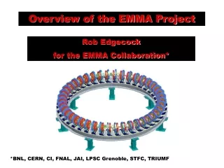
Project Overview • Electron Model for Many Applications (EMMA) • Will be the world’s first non-scaling FFAG • Part of a larger project called CONFORM ( COnstruction of a Nonscaling FFag for Oncology, Research, and Medicine ) www.conform.ac.uk/ • Project started on 2nd April 2007and it has a 3.5 year timescale • CONFORM is the 1st project of the BASROC consortium www.basroc.org.uk/ • 3 work packages to the project: • EMMA design and construction of a non scaling FFAG - £5.75m • PAMELA design study - £865k • Applications study - £273k
Aims & Objectives An EMMA objective: to understand the NS-FFAG beam dynamics as function of lattice tuning and RF parameters Tune plane (per cell) • Example: retune lattice to vary resonances crossed during acceleration Time of Flight vs Energy • Example: retune lattice to vary longitudinal Time of Flight curve, range and minimum Graphs courtesy of Scott Berg, BNL
DC Magnets • Offset quadrupoles provide independent dipole and quadrupole fields • Challenges: • High aspect ratio (“all ends and no middle”) • Wide aperture (+ lateral movement) • Proximity to each other and other devices • All magnets must be identical (to 0.1%)
DC Magnets (determined by inscribed radius) (determined by symmetry) Detailed pole profile design extend good gradient region over required aperture Clamp plates added to outside of doublet reduce stray fields, enable precise adjustment of integrated gradient Detailed 3D modelling and field maps produced assess effect of field overlap
Fast Magnets for Injection Injection Septum 65° Kicker Kicker Space is very limited!
Septum Parameters Max. beam deflection (injection) 65° Max. beam deflection (extraction) 70° Max. flux density in the gap 0.83 T Excitation pulse (half-sine-wave) 25 µS Peak excitation voltage 2 kV Peak excitation current 9 kA Repetition rate 20 Hz Conductor Circulating beam Septum Laminations Gap
Septum Measurement Techniques • Septum magnet field reached B=1T (125%) (<0.8T needed) . Long coil (integrated field) • Detailed field map B(x, y, z=0, t) available. • Max. stray field strength ~4x10⁻⁴ [Tm] (at 0.7 T gap field) • We need to estimate the impact of a stray field of that magnitude on the circulating beam. d=6mm Long curved coil (field integrated along the trajectory) Field map measurement
Summary of Septum Measurements • Septum magnet field reached B=1T (125%) (<0.8T needed) . Shielding added to reduce stray field • Detailed field map B(x, y, z=0, t) available. • Max. stray field strength ~4x10⁻⁴ [Tm] (at 0.7 T gap field) • We need to estimate the impact of a stray field of that magnitude on the circulating beam. 35 μs half-sine-wave pulse
Kicker Parameters Max. beam deflection 105 mrad Hor. good field region46 mm Min vertical gap 25 mm Hor. deflection quality± 1 % Min. flat top (+0 -1%)5 nS Field rise/fall time < 50 nS Repetition rate 20 Hz Physical length available100 mm Field strength 0.007 Tm Peak voltage 30 kV Peak current 1.3kA
Kicker Measurement Method • Rectangular coil, 300 mm long, 3mm thick; metallic layer (100 μm) on the appropriate sides. • Gives the integrated field strength. • Coil positioning with the Hall-probe bench. • Plans to make a detailed field map with a 6 mm diameter small coil didn’t quite work out: stray capacitance in the coil creates a resonance.
Kicker Measurement Results • Full kicker strength 0.007 Tm reached at 28 kV. • Ringing in the pulse tail does not seem to be as bad as the CT signal suggests. • Pulse fall-time ~70 ns (longer than the specified 50 ns). • In-situ field probes installed on all the kickers, tested and calibrated • Fine-tuning the injection kicker pulse shape by adjusting various circuit elements (a.k.a. knobs). • resistors • varistors (voltage-dependent resistors) • bias current
Normal conducting single cell design Frequency: 1.3GHz ± 5.6MHz Voltage: 20-120kV Power required: 3.6kW / cavity Manufacture and delivery of 20 production cavities (inc one spare) completed by Niowave High quality manufacture including electron beam welding of body to reduce distortion Chemical etching adopted to improve Q (Qo 18,500 to 20,400) RF Cavities Machining Cavities exceed EMMA specification Input Coupler Times Microwave E B welding
Electron Beam Position Monitors Production Coupler RF Detector, Clock, Control & ADC The BPM electronics system has to deliver 50 mm resolution over a large aperture for a single bunch of electrons on a turn-by-turn basis. Locally mounted coupler card amplifies and separates signals from opposite buttons in time, to give a 12nS delay between each. Signals combined and transmitted via a single high quality coax cable to…. ……VME based detector cards located in rack room outside of shielded area. Status:- All elements of the detector and digitisation stages are designed. Contract has been placed to design the VME interface.
Online Modelling Real EMMA Magnets, BPMs, RF, vacuum, PSS... EPICS IOCs High-level software Beam threading, tune measurement, ToF, ... Virtual EMMA ZGOUBI model: magnets, RF, BPMs EPICS IOC EPICS Channel Access layer An online model runs in the background in the control room, defining a virtual accelerator EPICS interface; we operate the VA in the same way as the real EMMA Allows high-level software to be tested offline(another VA instance local to your PC) Machine settings can be transferred between the VA and the real EMMA
Current Build Status • Latest results in ALICE eLog:http://alice.stfc.ac.uk/elog/alicelog/ Final module (M35 – extraction) was installed on 16 June 2010 EMMA 4-sector commissioning began on 20 June Full ring commissioning scheduled for August
Injection line commissioning YAG-3 YAG-5 YAG-1 YAG-6 YAG-2 YAG-4 A 15 MeV beam was successfully transported down the EMMA injection line in March 2010 Since then, the first section has been successfully used as a single-bunch energy spectrometer for ALICE
CONFORM Project Open Day EMMA PAMELA ADSR • CONFORM Project Open Day • Church House, London, 24th June http://www.hep.manchester.ac.uk/g/accelerators/conform/openday2010/ • Report progress on the project including • EMMA • PAMELA Design Study • Cell Studies • Accelerator Driven Subcritical Reactors • Opportunities for Industry • Next steps
Conclusions • EMMA will be an excellent machine to study the properties of non-scaling FFAG lattices • Designing and building this machine to spec has been challenging • DC magnets – wide aperture • Pulsed magnets – high field, short pulse • BPMs – single bunch, high accuracy • Full ring commissioning will take place in August 2010 • Thanks to everyone whose slides I’ve stolen for this talk • Mike Craddock (TRIUMF), Neil Bliss, Kiril Marinov, ...