Surge Protective Devices
Surge Protective Devices. UL 1449. UL 1449. UL 1449 has undergone 2 significant revisions in the past five years:
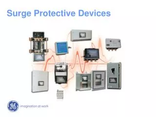

Surge Protective Devices
E N D
Presentation Transcript
UL 1449 • UL 1449 has undergone 2 significant revisions in the past five years: • In February of 2005, UL 1449 2nd Edition a major revision requiring additional safety testing at medium-fault current levels for TVSS. Compliance to this update became mandatory on February 9, 2007. • UL 1449 3rd Edition was published in September 2006 with full manufacturer compliance required by September 29, 2009.
UL 1449 3rd Edition Who did this affect…? All SPD manufacturers. The change was industry wide and compliance is mandated by UL and the National Electrical Code. Due to terminology and ratings changes, UL 1449 3rd Edition also significantly impacts customer master specification documents used for defining SPD requirements.
UL 1449 3rd Edition…Major Changes • 2nd Edition • Transient Voltage Surge Suppressor (TVSS) • For devices on circuits 600V or less • Surge Voltage Rating (SVR) • Duty Cycle Testing • Installation on load side only • Class A, B, C devices • 3rd Edition • Surge Protective Device (SPD) (Now includes Secondary Surge Arrestors) • For devices on circuits 1,000V or less • Voltage Protection Rating (VPR) • Nominal Discharge Current (In) • Type 1 devices can be installed on line side or load side • Type 1, 2, 3, 4 devices • UL1449 is now American National Standard (ANSI) The term SPD (Surge Protection Device) replaces TVSS (Transient Voltage Surge Suppressor) as the proper name for addressing surge protectors.
Voltage Protection Rating – (VPR) • An IEEE C62.41 cat. C-Low 6kV / 3000A combination surge wave is now used to benchmark SPD clamping performance. • Application of the test wave is done both prior to and after the Nominal Discharge Current Test (In) is performed. • Average clamping numbers result in the UL assigned Voltage Protection Rating (VPR) for each protected mode. • Surge Test Current is 6X greater than UL 1449 2nd Edition SVR test, which used a non-standard 6kV / 500A combination wave.
Voltage Protection Rating – (VPR) • Higher current levels will yield higher VPR ratings, when compared to 2nd edition SVR ratings for an identical device. Typical SVR range for 120/208V TVSS Typical VPR range for 120/208V SPD
Nominal Discharge Current – (In) • Value is selected by the manufacturer • Type 1 SPD can be either 10kA or 20kA • Type 2 SPD can be 3kA, 5kA, 10kA or 20kA • Nominal discharge current level is marked on the label of SPD • Test subjects SPD to a total of 15 impulses • In order to successfully pass test: • SPD cannot create a shock or fire hazard during the test • SPD must remain within 10% voltage clamping tolerance of the VPR rating
Lightning Protection Systems – (LPS) • UL96A – Installation Requirements for Lightning Protection Systems • Now allows for a Type 1 or Type 2 SPD rated 20kA nominal discharge current (In) • All GE SPD devices rated from 65kA to 300kA per mode are now suitable for use on UL96A installations.
Lightning Protection Systems – (LPS) The SPD Requirements of UL96A were updated in 2007 to align with UL 1449 3rd Edition, allowing Type 1 or Type 2 SPDs rated with UL nominal discharge current (In) of 20kA as an option for the mandated SPD for Lightning Protection Systems. It should also be noted that UL currently will not approve non-UL Listed SPDs for use in UL96A systems. This included ETL, MET-Labs or other NRTLs.
GE SPDs for LPS - (In) Rating • All GE SPDs, surge-rated between 65kA-300kA per mode models carry a UL Nominal Discharge Current rating of 20kA. This is the highest rating of (In) that is currently assigned by UL. • GE SPDs for branch panel and point of use applications carry a 10kA (In) rating. GE SPDs rated 65kA –300kA 20kA (In) GE SPDs rated 25kA –50kA 10kA (In)
UL SPD Location Types Type 1 – Permanently connected SPDs intended for installation between the secondary of the service transformer and the line side of the service equipment overcurrent device, as well as the load side, including watt-hour meter socket enclosures and intended to be installed without an external overcurrent protective device.. Type 2 – Permanently connected SPDs intended for installation on the load side of the service equipment overcurrent device; including SPDs located at the branch panel. Type 3 – Point of utilization SPDs, installed at a minimum conductor length of 10 meters (30 feet) from the electrical service panel to the point of utilization, for example cord connected, direct plug-in, receptacle type and SPDs installed at the utilization equipment being protected. The distance (10 meters) is exclusive of conductors provided with or used to attach SPDs. Type 4 - Component Assemblies – Component assembly consisting of one or more Type 5 components together with a disconnect (integral or external) or a means of complying with the UL 1449 limited current tests. Type 1, 2, 3 Component Assemblies – Consists of a Type 4 component assembly with internal or external short circuit protection. Type 5– Discrete component surge suppressors, such as MOVs that may be mounted on a PWB, connected by its leads or provided within an enclosure with mounting means and wiring terminations.
GE SPD Ratings - Type 1 • All GE SPDs that begin with a part number suffix of “TP” are now available as a UL Type 1 device by adding a part number suffix of “T1” to the standard part number. • Type 1 SPDs can be installed at any location within the low voltage electrical distribution system on either the utility or load side of main service breaker. • Type 1 SPDs are not cUL listed. Instead they are UL only. CSA standards do not recognize a Type 1 SPD application. • Applications for Type 1 SPDs include: • Main Lug Only service entrance panels where the SPD is installed parallel to multiple service disconnects. • Multi-dwelling residential complexes between utility and meter stack. • Remote buildings or structures that do not include primary overcurrent protection.
GE SPD Ratings - Type 2 • All GE SPDs models numbers that were previously listed under UL1449 2nd Edition will now have a UL Type 2 rating. • Type 2 SPDs are the same as devices previously called TVSS. Per NEC 285.24, Type 2 devices can only be installed on the load side of the main breaker within the low voltage electrical distribution system. • If a GE model number is selected that does not have a “T1” suffix designator, it will be a UL Type 2 device.
GE SPD Ratings • GE SPDs did not require design modification, nor introduce new models in order to comply with UL 1449 3rd Edition. As a result, the following ratings will remain unchanged: • IEEE C62.41 Clamping Voltages • Maximum Single Impulse Surge Ratings • Repetitive Surge Current Ratings (Surge Life Testing) • EMI/RFI Filtering Characteristics • UL SCCR • MCOV
Customer Specifications Many customer specifications still do not yet reflect the terminology and ratings changes that are now in effect under UL 1449 3rd Edition and the National Electrical Code. GE’s Latest Specification Format Recently Submitted Customer Spec Example Requiring SVR Ratings:
SPD Application Considerations • Cascading System Wide Protection • ANSI/IEEE 1100 Emerald Book Guide for Powering and Grounding • Suggests cascading SPD approach for all categories and exposure levels • Higher level voltage spikes can get past service entrance • Voltage spikes from high kA transients can still damage downstream equip • Internally generated transients – Account for60% or more of all transients • Service entrance TVSS cannot provide protection from internal surges • Unexpected external transients in distribution – ie Rooftop AC • Lightning strikes on building or nearby bring high kA transients into distribution • Redundant layered protection at multiple levels • Additional layers protect sensitive electronics if upstream devices fail
Main … … … … … … Transformer … Trans former Surge Location Categories ANSI/IEEE C62.41 Surge Exposure Risk Location Categories A/B/C External Transient Sources A/C Internal Transient Source Sensitive Loads IEEE Cat. C Primary IEEE Cat. A MDP Main … Secondary Security Computers Video UL Type 2 SPD Internal Transient Sources Drives Motors IEEE Cat. C/B Transitional Area IEEE Cat. B IEEE Cat. B/A Service Entrance Line Side – Type 1 SPD Load Side – Type 2 SPD Primary Distribution Type 2 SPD Secondary Distribution Type 2 SPD Point of Use Type 2 SPD Type3 SPD
SPD Application - GE Ratings Single Surge Rating (Per Mode) HE - High Exposure 125 – 300 kA IEEE Category C Service Entrance Locations ME - Medium Exposure 65 – 100 kA IEEE Category B Primary and Secondary Distribution Locations LE - Low Exposure 25 – 50 kA IEEE Category A Long Branch Panel and Point of Use Locations
GE SPD Options Wall Mounted New Construction Add to existing facility electrical distribution When branch panel disconnect is required Integral Switchboard & Panelboard OEM Electrical Panel / Equipment Shops New Construction New panels or switchboards on existing facility Panelboard Extension Add to existing facility electrical distribution When branch panel disconnect is required
GE Wall Mounted SPDs UL Listed models for both Type 1 and Type 2 Locations UL Nominal Discharge Current Rating = 20kA (In) UL96A Compliant Surge Ratings available from 25kA – 300kA per mode. NEMA 1, 12, 4, and 4X Stainless NEMA 12 Flush-mount Surge Life Ratings from 3,500 – 20,000 impulses @ 10kA / 8x20us Optional features include: Surge Rated Disconnect, Surge Event Counter, Audible Alarm with Test/Silence, EMI Filter, Remote Alarm Contacts.
GE Integral Mounted SPDs Factory Installed by GE in Switchboard, Switchgear, MCC, and Panelboards. UL Listed models for both Type 1 and Type 2 Locations UL Nominal Discharge Current Rating = 20kA (In) UL96A Compliant Surge Ratings available from 65kA – 300kA per mode. Surge Life Ratings from 5,000 – 20,000 impulses @ 10kA / 8x20us Standard features include: Surge Rated Disconnect, Surge Event Counter, Audible Alarm with Test/Silence, EMI Filter, Remote Alarm Contacts.
GE SPD Design – MOV GE TLE, TME and THE series models are equipped with large duty, dual wafer 48mm MOVs. Each MOV is surge rated at 100kA (8x20us) A large number of manufacturers use smaller MOVs in large quantity arrays.
SPD Design – Small MOV Modal Array The Requirement for Exact Matching of MOV’s presents a Potential Problem. MOV’s are non-linear components. Factory matching with 1ma. DC test levels does not always mean the same clamping performance will be realized at higher energy surge levels High-Energy Surge Event (>10kA) Weakest MOV’s cannot withstand energy level and fail Other poorly matched MOV’s are left in a degraded state.
GE SPD Design – MOV Features GE TPME and TPHE series models are equipped with Enhanced Thermally Protected Metal Oxide Varistor Technology Robust 34 mm2 MOV design. (Equal to 40mm round MOV’s) Thermal Disconnect with proprietary eutectic bond to MOV body. High dielectric strength arc suppression shield. All GE Integral SPDs designs are equipped with Thermally Protected MOV’s.
GE SPD Design –Disconnect Low Impedance Surge Rated Disconnect Switch Independent test facility verification for 200kA – 8/20us withstand (Optional on Some Models / Recommended when direct bus mounting is required)
GE SPD Design – Fusing *Surge Rated Current Fuses *TPME and TPHE Series do not require current limiting fuses due to their enhanced thermal disconnect feature. Surge Fusing included on TME and THE models only.
GE SPD Design – Summary All components that are used in GE SPD products have been tested at the maximum rated capability of the SPD. In the past there have been a selective few SPD manufacturers will omit or bypass certain components in order to achieve the maximum ratings. This is possible, due in part to specifications that do not require disclosure of components that are included in the surge path of tested sample. Always request comprehensive 3rd Party Test data that includes this information.
GE SPD Design – Summary Example of 3rd Party Test Document that describes included components
SPD Application – Wire Length Each 1-inch length of SPD connecting wire can account for increased surge clamping voltage levels. Based on a number of empirical studies, it is estimated that the potential decrease in clamping performance can vary from as little as 6 volts per inch, to as much as 25 volts per inch. (70-300 volts per foot)
SPD Application – Wire Length Wire Length Effects Study • In 2004, GE contracted R&B Laboratories NVLAP accredited Lab located in Conshohocken PA to perform surge testing on a simulated electrical distribution system with SPD installed. • The purpose of the test was to determine the effects of cable length on SPD performance. • Both integrally mounted and wall mounted SPD designs were included in the test. • Wall Mount SPD were evaluated when connected at lengths of 3’ and 10’. • Integral SPD were connected to the distribution equipment bus. • Standard IEEE surge waveforms were injected at the main lugs of the electrical panel. • Let thru voltages were captured and recorded downstream from the SPD panel on both the primary and secondary side of a step-down transformer.
SPD Application – Wire Length Wire Length Effects Study Integral Configuration Wall Mount Configuration
SPD Application – Wire Length Wire Length Effects Study
SPD Application – Wire Length Wire Length Effects Study Conclusion • Independent testing confirms that the effectiveness of otherwise equally rated SPDs is directly related to connection method and length of wire leads. • The length of SPD wire and applied surge energy had the most impact on the basic protection level offered by the SPD. • The length of SPD wiring is the most critical variable that can be controlled in real world installations. • UL SVR (now VPR) ratings are sometimes used as a critical specification parameter for comparing SPD surge clamping capabilities. However, based on the findings of this study, an even greater emphasis should be placed on the SPD installation method, rather than a benchmark study that only defines the performance of all SPD as being connected 6” from the power source.
SPD Application – Wire Length Wire Length Effects Study In May, 2005 the Wire Length Effects study was presented at the IEEE Industrial and Commercial Power Systems Technical Conference. The final report was published by IEEE as ISBN report no. 0-7803-9021-0
SPD Value PropositionWhy Our Customers Need SPD ? TVSS provides the means to protect infrastructure and sensitive electronic equipment against damaging transient surges generated both inside and outside of facilities. Fully 60% - 80% of the transients surges are actually generated inside the building from environmental equipment. Examples include HVAC, elevators, conveyors, compressors and laser copiers. Surge Protection Devices reduce wear and tear on all electrical and electronic circuits including lighting ballasts. When the total cost of all electronic devices connected to a power distribution system in a building is considered, Surge protection is inexpensive insurance.
Utility Power SPD UPS $ Impact SPD Safeguard critical equipment & reduce costly repairs UPS Provide power during outages and save critical data Voltage Spikes Line noise Sags / Swells Outages Protect sensitive electronic equipment Filter out noise EMI/RFI Provide uninterruptible power during outage Condition utility power • SPD Value Proposition • Power quality has an economic impact
SPD Value Proposition SPD Needs Assessment Protect sensitive electronics from damaging transient surges for a fraction of connected equipment value $ $ $ SPD = Affordable Insurance • Estimated $ value of sensitive electronic equipment ? • Damaged, degraded, lost equipment from electrical failure ? • Cost of down time or shutting down your facility ? • Security risk when alarms/surveillance equipment fail ? • Are my facilities unprotected now ?
SPD Value Proposition SPD Needs Assessment Actions to take : Tour customer’s facility to review electrical distribution system Evaluate sensitive electronic equipment in need of protection Start with sensitive electronics and work to service entrance Make recommendations on locations, type and quantity of SPD needed to ensure a properly protected system
GE SDP Products Tranquell SeriesRatings Per Mode HE - High Exposure 125 – 300 kA ME - Medium Exposure 65 – 100 kA LE - Low Exposure 25 – 50 kA
GE SPD Advantages of a GE SPD System Complete Product Line up Integral and Wall mounted devices ranging from 25 – 300kA max single impulse at 65kAIC and 200kAIC per mode for use throughout the electrical distribution system State of the Art Engineering Max Surge Current 3rd Party Tested per NEMA LS-1 test standard with complete documentation. Every TVSS up to 200kA per mode is fully rated and tested including fuses at six inch leads. * Note there are no labs that can test over 200kA per mode Excellent Surge Clamping Performance per UL 1449 2nd edition Suppressed Voltage Rating (SVR) for all levels of electrical distribution system including service entrance, distribution and point of use locations Outstanding Longevity Characteristics Life cycle tested to 5,000, Tranquell ME and 20,000, Tranquell HE C3 (10kA) 8x20 us repetitive surge impulses, and 5,000 (2kA) 10 x 1000 us on both the Tranquell HE and ME. 5 year standard warranty option to 10 year
New Product launch Din Rail Surge Protective Device (SPD) UL and cUL version
Product Features Remote indicator/contacts (NO, NC, COM) Built-in visual indicator Pluggable, IP20 finger safe Small footprint
End Users examples Telecom Cabinets Automation Control Cabinets Motor Control Cabinets Security System Cabinets Cell Tower Sites Digital Billboards
Resources • Web site www.GECriticalPower.com
Resources • Publications (PDFs) posted on web site