Engineering with Wood
350 likes | 518 Vues
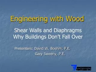
This presentation by David W. Boehm, P.E., and Gary Sweeny, P.E., delves into the critical role of wood shear walls and diaphragms in strengthening building structures against seismic forces. By examining load distribution, nailing specifications, and diaphragm layouts, the speakers illustrate how to prevent structural failure during seismic events. Attendees will gain insights into safe design practices, including shear wall calculations with openings and methods to withstand overturning moments, making it essential for engineers working in seismic zones.

Engineering with Wood
E N D
Presentation Transcript
Engineering with Wood Shear Walls and Diaphragms Why Buildings Don’t Fall Over Presenters: David W. Boehm, P.E. Gary Sweeny, P.E.
l = 120’ 200 x 402 x 120 vew = wew x b = = 33 #/FT 2 x l 200 x 120 2 x 40 vns = wns x l = = 300 #/FT veu wew= 200#/FT b=40’ vns wns = 200#/FT DIAPHRAGM UNIT SHEARS 2 x b
PANEL LAYOUT AND FASTENER SCHEDULE North-South Loading Case 1 v = 300 #/FT Assume 8 d nails 15/32 plywood 2” nominal framing Choose: Blocked Diaphragm 8 d nails @ 4” panel edges 8 d nails @ 6” interior East-West Loading Case 3 v = 33 #/FT Unblocked 6” max spacing at panel edges
DIAPHRAGM CHORD SIZE Moment due to N-S wind m = wl 2 = 200 1202= 360,000 FT-LBS 8 8 Axial load in chords = C = T = M = 360,000 ft-lbs = 9,000 LBS b 40 ft Assume allowable ft = 1150 psi Area required = 9,000# = 7.8 in2 1150 psi Assume 2 x 8 wall plate, bolted Area of 2 x 8 with bolt hole A = 1.5 x (7.25 - .875) = 9.56 in2 Use double 2 x 8 top plate / chord to allow for splice
A 40’ T C Shear Walls • North wall v=33 #/ft • Nominal nailing required • East and west walls v=300 #/ft Vns = 300#/ft(40’) = 12000# 20’ Nailing pattern 7/16 sheathing2 x studs8d nails @ 4” required Shear wall elevation
Tiedown Force ΣMA = 0 0 = (12000 x 20) – (T x 40) T = 6,000#