Download

1 / 19
190 likes | 631 Vues
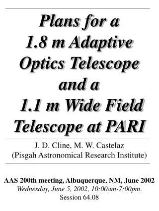
Plans for a 1.8 m Adaptive Optics Telescope and a 1.1 m Wide Field Telescope at PARI J. D. Cline, M. W. Castelaz (Pisgah Astronomical Research Institute) AAS 200th meeting, Albuquerque, NM, June 2002 Wednesday, June 5, 2002, 10:00am-7:00pm . Session 64.08

E N D
Plans for a 1.8 m Adaptive Optics Telescope and a 1.1 m Wide Field Telescope at PARI J. D. Cline, M. W. Castelaz(Pisgah Astronomical Research Institute) AAS 200th meeting, Albuquerque, NM, June 2002Wednesday, June 5, 2002, 10:00am-7:00pm. Session 64.08
Radio and Optical Observatories at the Pisgah Astronomical Research Institute (PARI) • PARI is • a not-for-profit public foundation • dedicated to providing research and educational access to radio and optical astronomy for a broad cross-section of users • PARI is located on 200 acres in the Pisgah Forest west of Asheville, NC • The site is relatively free of light and radio interference
Aerial View of the PARI Campus N 26-m East Optical Ridge 26-m West 12-m • For use by Visiting and Resident scientists: • Two 26-m radio telescopes, one 12.2 m radio telescope, one 4.6 m radio telescope, several dedicated optical telescopes • Locations for future telescope development • Lab and Office Space
The Radio Telescopes Two 26-m radio telescopes with 1.42, 4.8, 6.7, and 12.2 GHz receivers are shown here. The telescopes slew, set, guide, and track. They can be operated together (300 m near E-W baseline) or separately. 26 m West 26 m East
The 4.6-m radio telescope feeds include 1.42, 4.8, 6.7, and 12.2 GHz. This telescope is used for education/public outreach through the School of Galactic Radio Astronomy (SGRA; this meeting Session 47.03). 4.6-m The 12.2-m antenna is available for consortium sponsorship and use at frequencies up to 60 GHz. 12.2-m prime focus feed
The PARI Optical Ridge Aerial Image of the Optical Ridge. At an altitude of 910 m, the ridge runs East-West with steep sloping sides to the North and South. The highest point on the horizon is 5 degrees, with an average of 2 degrees. The 1.8 m and 1.1 m locations are shown (red), along with existing telescopes (blue). Lat: 35d 11.828m N, Long: 82d 52.346m WAltitude: 934
Telescopes Other Than the 1.8 m and 1.1 m on the PARI Optical Ridge • Questar (18 cm, f/14.3, 81.2 arcsec/mm), 2k x 2k 13 um/pix CCD 36 arcmin FOV), UBVRI filters • Solar/Lunar 12.7 cm telescope with SBIG STV, live video feed to Internet • All-sky fisheye 24 hour telescope • Polaris continuous photometry telescope • Atmospheric Seeing/Transparency 24-hour monitoring 12.7 cm telescope and SBIG STV • 0.2 m telescope for Galactic Plane Survey, operating since October 2000 • 0.28 m telescope for gamma ray burst afterglow
Plans for a 1.8 m Adaptive Optics Telescope • 4 cm Thick Fused Silica Adaptive Optics Mirror • F-Ratio = 1.5 • Spherical Surface Figure • Wavefront Errors = l/50 (l/30 allotted to steady state operational dynamics)
Characteristics of the 1.8 m Adaptive Optics Primary Mirror Cell • Three Flexural Supports • 40 Actuators to a Back Structure • Cell Weight = 1400 lbs • Mirror Weight = 550 lbs Mirror One of the actuators is shown. The back of the mirror is coupled to the actuator through a glass block for thermal insulation. Glass Block Actuator
Telescope Definition Telescope definition is an open issue and depends on input from the astronomical community. Suggestions for use and design beyond those listed below are welcome. Please feel free to contact us (e-mail dcline@pari.edu) or leave a note here for us to contact you.. Telescope Uses and Designs under consideration: • Large Field Prime Focus Camera for • Gamma Ray Burst Afterglow Photometry • Supernova Search • Near Earth Object Search • LIght Detection And Ranging (LIDAR) for atmospheric research • High Resolution (0.01 A/pix) Spectrometer
Plans for a 1.1 m Wide Field Telescope The telescope will be field corrected prime focus camera with a 1.73 degree diameter field of view. • The primary mirror is a 1.1 m f/4.4 fused quartz (honeycomb) substrate, coated • Scale 41.5 arcsec/mm • Conic constant –1.900 +/- 0.005 The Primary Mirror
Characteristics of the Field Corrector at Prime Focus We have set the condition that image quality in the focal plane will not be limited by telescope optics, rather by seeing and mechanical effects. To meet this condition, a 3-element field corrector, will be used to focus a 15 cm diameter focal plane. The table below summarizes the properties of the corrector. All lenses are made of BK7 glass. Lens 1 is nearest to the primary mirror at a distance of 391.35 cm, and Lens 3 is 7.16 cm from the focal plane.
Prime Focus Optical Layout The prime focus is formed by three lenses comprising a corrector. Shown here is the third of the lenses, along with the shutter, and two guide cameras. Light in the center 10 cm square field (1.15o) is the science field. Two guide cameras are located 180o apart in the fields formed by the 15 cm diameter field and chords along the science field. A third chord area will hold several fiber optics for a future spectrograph.
With the field corrector, the RMS wavefront error is less than the diffraction limit to the edge of the 15 cm focal plane. • Figure below shows spot diagrams within 1 arcsec boxes on the optical axis and at the edge of the 15 cm focal plane, respectively. • The image size approaches one arcsecond at the very edge of the field of view. • The science field is a 10 cm square, so the optics produce less than one arcsecond images in the entire science focal plane. Spot diagrams based on the prime focus corrector for the 1.1 m telescope. The boxes are 24 microns, or 1 arcsec on a side. a) The spot diagram on the optical axis, b) the spot diagram 7.65 cm from the optical axis.
Telescope Assembly The open structure optical tube telescope mount we plan to use is the DFM Engineering equatorial mount, shown above. The DFM 1.27 m polar axle and support telescope mount will be customized for the 1.1-m mirror.
Atmospheric Seeing and Transparency Measurement Instrumentation Weather Station: probes for temperature, humidity, pressure, wind, rain. All-Sky Camera: Live video of the sky through a fisheye lens. • Polaris Telescope: • Continuous 24-hour monitoring of atmospheric transparency and seeing conditions • 0.25 m telescope with CCD plus UBVRI filters; 81 arcsec/mm or 0.60 arcsec/pixel • Bright Star Telescope: • Robotic 12.7 cm f/10 telescope with CCD • Measures flux of bright (V<2.5) stars 24 hours a day • Software automatically points telescope, images, does photometry and outputs stellar magnitude and sky brightness • outputs seeing measure based on area bright stellar image covers on CCD chip • outputs transparency measure based on ratio of stellar/sky surface brightness.
The Bright Star Telescope is seen in its clear dome The information from the Bright Star Telescope and the other seeing/transparency instruments build a database of atmospheric conditions accessible to other telescopes of the PARI Observatories and observers using the telescopes remotely.
We are open to new consortia to develop projects at PARI, or an established consortium to enhance their research and education opportunities with projects at PARI including development and support of existing or new telescopes at PARI. Contact: Don Cline (dcline@pari.edu)Or Michael Castelaz (mcastelaz@pari.edu) Pisgah Astronomical Research Institute 1 PARI Drive Rosman, NC 28772 Internet: www.pari.edu Office: 828-862-5554FAX: 828-862-5877Internet: www.pari.edu