Download
1 / 20
220 likes | 518 Vues
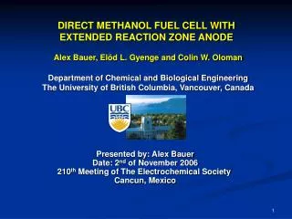
DIRECT METHANOL FUEL CELL WITH EXTENDED REACTION ZONE ANODE. Alex Bauer, Elöd L. Gyenge and Colin W. Oloman Department of Chemical and Biological Engineering The University of British Columbia, Vancouver, Canada.

E N D
DIRECT METHANOL FUEL CELL WITH EXTENDED REACTION ZONE ANODE Alex Bauer, Elöd L. Gyenge and Colin W. Oloman Department of Chemical and Biological EngineeringThe University of British Columbia, Vancouver, Canada Presented by: Alex BauerDate: 2nd of November 2006210th Meeting of The Electrochemical Society Cancun, Mexico
DMFCs for portable applications (and transportation) Anode reaction: CH3OH + H2O CO2 + 6H+ + 6e-E0a= 0.04 V@ 298 K Methanol:-cheap (ca. 200 $ US/t) - easy handling, storage and distribution - simple fuel cell design and operation [1] [1]W. Zittel, R. Wurster, HyWeb: Knowledge – Hydrogen in the Energy Sector http://www.hydrogen.org/Knowledge/w-i-energiew-eng2.html
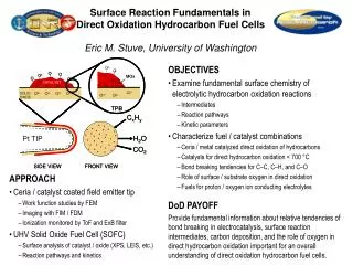
Current challenges and potential solutions Sluggish anode reaction Development of novel catalysts (ternary and quaternary compositions) Enhancing active catalyst area (nanoparticle – support interaction) Methanol cross-over Modified membranes CO2 accumulation Hydrophobic channels (PTFE addition) Alternative flow designs (e.g. mesh flow beds) Novel electrode designs OUR APPROACH: Application of porous 3D catalyzed graphite felt electrode with high specific surface area
Recent developments for DMFC anode designs PtRu particles d = 2 - 3 nm Carbon 500 nm 100 nm [2] G. S. Chai et al., J. Phys. Chem. B, 108, 7076 (2004) Ti mesh PtRu particles d 5 nm [3]R. G. Allen et al., J. Power Sources, 143, 145 (2005)
DMFC with conventional anode e- O2(g) diffusion layer 100-300m H+ catalyst layer end plate 15-50m membrane CH3OH (l) Anode reaction: CH3OH + H2O → CO2 + 6H+ + 6e- Cathode reaction: 1.5O2 + 6H+ + 6e-→ 3H2O
DMFC with novel 3D anode e- O2(g) catalyzed graphite felt H+ 100-200m depending on compression CH3OH (l) Anode reaction: CH3OH + H2O → CO2 + 6H+ + 6e- Cathode reaction: 1.5O2 + 6H+ + 6e-→ 3H2O
Surfactant assisted electrodeposition to obtain porous catalyst deposits [4] 2-15 nm Smooth substrate [4] B. Gollas et al., Electrochimica Acta, 45 (22), 3712 & 3721 (2000) Without surfactant With surfactant [5] [5] 3D graphite substrate [5] A. Bauer et al., Electrochimica Acta, 51 (25), 5359 (2006)
+ - DC power supply graphite felt (cathode) plastic mesh separator plexiglass cell containing plating solution platinized Titanium anodes Surfactant assisted galvanostatic deposition of nanoparticles on 3D substrate graphite felt substrate [6] • 0.95, d 350 m, as 104 m-1 [6] A. Bauer et al., Electrochimica Acta, 51 (25), 5358 (2006)
Research objectives • Surfactant mediated electrodeposition of PtRu and PtRuMo catalyst on graphite felt • Analysis of deposit morphology, weight, composition and active surface area (SEM, ICP_AES, Cu upd) • Assessment of catalytic activity for methanol oxidation (CV,CP,CA) • Fuel cell testing Overall goal: Assess feasibility of employing catalyzed graphite felt as DMFC anode for liquid feed operation.
Results - SEM ► ◄ ~ 50 nm High resolution SEM micrograph of PtRu catalyst deposited on graphite by surfactant assisted galvanostatic plating
Results – Cyclic voltammetry Scan rate = 5 mV s-1, 0.5 M CH3OH - 0.1 M H2SO4
Results – Chronopotentiometry Current = 5 mA cm-2, 0.5 M CH3OH - 0.1 M H2SO4
Results – FC tests: Novel 3D anode vs. conventional gas diffusion electrode (GDE) Anode: 1 M CH3OH - 0.5 M H2SO4, 5 ml min-1, ambient pressure Cathode: dry O2, 500 ml min-1 STP, 2 atm
Results – FC tests: Novel 3D anode vs. conventional gas diffusion electrode (GDE) Anode: 1 M CH3OH - 0.5 M H2SO4, 5 ml min-1, ambient pressure Cathode: dry O2, 500 ml min-1 STP, 2 atm
Results – FC tests: Novel 3D anode PtRu vs. PtRuMo Anode: 1 M CH3OH - 0.5 M H2SO4, 5 ml min-1, ambient pressure Cathode: dry O2, 500 ml min-1 STP, 2 atm
Results – FC tests: Novel 3D anode PtRu vs. PtRuMo Anode: 1 M CH3OH - 0.5 M H2SO4, 5 ml min-1, ambient pressure Cathode: dry O2, 500 ml min-1 STP, 2 atm
Results – Deactivation tests in fuel cell i = 400 mA cm-2 T = 353 K gel: 1 M H2SO4, 5 %wt SiO2 Anode: 1 M CH3OH - 0.5 M H2SO4, 5 ml min-1, ambient pressureCathode: dry O2, 500 ml min-1 STP, 2 atm
Comparison of fuel cell performance with standard MEA and published data [7] C. Coutanceau et al., J. Appl. Electrochem., 34, 64 (2004) [8] G. S. Chai et al., J. Phys. Chem. B, 108, 7078 (2004) [9] R. G. Allen et al., J. Power Sources, 143, 148 (2005)
Conclusions and outlook • Obtained highly dispersed nanoparticles on 3D substrate • Improved performance compared to conventional GDE (e.g. power output increased by 38 % at 300 mA cm-2) • Proof of concept for novel electrode design Future work: • Optimize FC operation conditions (experimental design) • Develop ionic conductor network • Improve long term performance - especially for PtRuMo (e.g. catalyst regeneration after 2 h)
Acknowledgements The authors gratefully acknowledge the financial support of the BC Advanced Systems Institute and the Natural Sciences and Engineering Research Council of Canada.