BPA - WISP Project
BPA - WISP Project. NASPI Work Group Meeting October 12-13, 2011 Scott Lissit – Project Manager, Integration Lawrence Carter – Project Manager, PMU Installation Nick Leitschuh – Control Center Lead Dmitry Kosterev – Transmission Planning. Project Overview. Phase 1 - WISP. Phase 2.


BPA - WISP Project
E N D
Presentation Transcript
BPA - WISP Project NASPI Work Group Meeting October 12-13, 2011 Scott Lissit – Project Manager, Integration Lawrence Carter – Project Manager, PMU Installation Nick Leitschuh – Control Center Lead Dmitry Kosterev – Transmission Planning
Project Overview Phase 1 - WISP Phase 2 • PMU Installation • ~132 PMUs • 45 sites (32 500kV sites, 13 230kV sites) • 10 wind sites (data only) • No DOE funding used. Matching SGIG grant goes to WECC • Control Center network design/install • Situational awareness applications (near-term) • SynchroPhasor RAS development • SP RAS deployment • Additional applications • Wind site integration Apr 2010 Apr 2011 Apr 2012 Apr 2015 Apr 2014 Apr 2013
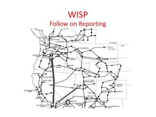
New PMU, Group 1 New PMU, Group 2 New PMU, Group 3 New PMU, Group 4 Existing PMU Existing/Replace PMU, Group 1 Existing/Replace PMU, Group 2 Existing/Replace PMU, Group 3 BPA PMU Deployment
PMUs • SEL 487e chosen, with customized features: • Multicast capability • On-the-fly configuration for main/aux bus • Two fully-configurable data streams from a single PMU (PDCs and RAS) • Stand-alone units, deployed in pairs or quads • IEEE C37.118 standard, M-class • 60 samples per second • Measurements: • Voltage and line current phasors in polar format, bus frequency, calculated line MW and MVAR, PCB and MOD statuses • No PDCs in substations
PMU Installation • Redundant PMUs with redundant communication paths (to two control centers) • Current Status: • “Standard” designs complete • 6 PMUs installed at 2 initial “Beta” sites • “Beta” data being analyzed • Contractor installation (Wilson/SAIC) • Schedule • Group 1 (Sites 3 – 14): February, 2012 • Group 2 (Sites 15 – 26): June, 2012 • Group 3 (Sites 27 – 40): October, 2012 • Group 4 (Sites 41 – 45): March, 2013 • Wind sites 1-10: December 2012
Communications Network • BPA-operated telecom network • SONET backbone • Digital microwave with legacy analog microwave • PMU network is IP over TDM using fractional T1s. UDP protocol. • High-capacity routers chosen to enable migration to future applications (Ethernet devices) and evolution of PMU requirements • RAS performancedriving design (latency requirements) • NERC CIP compliance driving design, network monitoring • Telecom backup battery and charger replacement required at most sites
Control Centers • Redundant PDCs in each control center • Currently in testing, final selection not yet made • Control Center Architecture • Evaluating feasibility of in-house design based on OSI PI architecture and dedicated application server • Data archives in each control center (short-term), and lab (long-term) • Currently in testing, final selection not yet made • Responsible for PMU network monitoring and NERC CIP compliance • WISP WAN gateway • Communications link between control centers
Applications • Strategy: Deploy “WASA light” and WECC shared view in Phase 1. • Situational Awareness • Phase angle alarm • Event detection • Oscillation Detection • Mode Meter (Montana Tech) • Engineering Applications • Event analysis • Dynamic performance baselining • Model validation • Other applications under development by BPA Technology Innovation: • Robust state estimation and contingency analysis • Wide area visualization
BPA WASA Strategy Wide-Area View: SCADA, PMU, Results of Contingency Analysis Trend Displays (PMU, SCADA) Dashboard Alarms PRESENTATION • Measurement-Based Applications: • Event Detection • Oscillation Detection • Mode Meter • Model-Based Tools: • Contingency Analysis • State Estimation • Measurement-based Tools: • Dynamic reactive reserve monitor • Phase angle monitor … ANALYTICAL APPLICATIONS Synchro-phasors SCADA DATA
Wide Area Controls PHASE 1 • Developmental version of PMU-based Remedial Action Scheme (RAS) Testing System Test Controller Running Response Based Logic Historical Data Simulated PMU data streams Raw Data Inject errors, delays, bad data, etc User values Digital Outputs
500-kV Line A-B Line Loss Logic Existing RAS Controller SWITCH Existing Local Controller Voltage Set-Point Switching Sequence 500-kV Line B-C Line Loss Logic Measured Local Voltage … Response- Based Logic Controller Wide-Area Measurements PHASE 2 Build on Existing Control Architecture
Challenges • PMU Installation • Short timeline • Scheduling equipment outages • Telecom • Equipment selection impacted by RAS latency requirements, and bandwidth for future traffic • Necessity for upgrades of back-up batteries and chargers at substations • Cyber security • PMUs will be CCAs, with associated PSP, ESP and operational requirements • Selection/development of near-term situational awareness applications and environment (compatibility with legacy systems) • Training for operations and maintenance of new equipment and network
Contact Information • Scott Lissit, PM 360-619-6415 salissit@bpa.gov • Lawrence Carter, PM (PMU Installation) 360-619-6675 ldcarter@bpa.gov • Nick Leitschuh, PM (Control Center, SA Apps) 360-418-8739 nleitschuh@bpa.gov