GR2 Advanced Computer Graphics AGR
GR2 Advanced Computer Graphics AGR. Lecture 12 Solid Textures Bump Mapping Environment Mapping. Marble Texture. Y. object space. V. texture space. U. X. W. Z. Solid Texture. A difficulty with 2D textures is the mapping from the object surface to the texture image

GR2 Advanced Computer Graphics AGR
E N D
Presentation Transcript
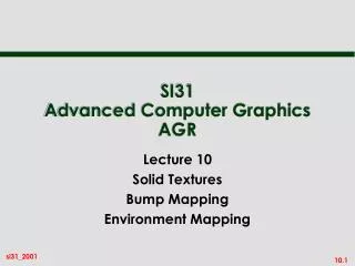
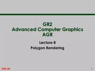
GR2Advanced Computer GraphicsAGR Lecture 12 Solid Textures Bump Mapping Environment Mapping
Y object space V texture space U X W Z Solid Texture • A difficulty with 2D textures is the mapping from the object surface to the texture image • ie constructing fu(x,y,z) and fv(x,y,z) • This is avoided in 3D, or solid, texturing • texture now occupies a volume • can imagine object being carved out of the texture volume Mapping functions trivial: u = x; v = y; w = z
Defining the Texture • The texture volume itself is usually defined procedurally • ie as a function that can be evaluated, such as: texture (u, v, w) = sin (u) sin (v) sin (w) • this is because of the vast amount of storage required if it were defined by data values
V texture space U W Example: Wood Texture • Wood grain texture can be modelled by a set of concentric cylinders • cylinders coloured dark, gaps between adjacent cylinders coloured light radius r = sqrt(u*u + w*w) if radius r = r1, r2, r3, then texture (u,v,w) = dark else texture (u,v,w) = light looking down: cross section view
Example: Wood Texture • It is a bit more interesting to apply a sinusoidal perturbation • radius:= radius + 2 * sin( 20*) , with 0<<2 • .. and a twist along the axis of the cylinder • radius:= radius + 2 * sin( 20* + v/150 ) • This gives a realistic wood texture effect
How to do Marble? • First create noise function (in 1D): • noise [i] = random numbers on lattice of points • Next create turbulence: • turbulence (x) = noise(x) + 0.5*noise(2x) + 0.25*noise(4x) + … • Marble created by: • basic pattern: • marble (x) = marble_colour (sin (x) ) • with turbulence: • marble (x) = marble_colour (sin (x + turbulence (x) ) )
Bump Mapping • This is another texturing technique • Aims to simulate a dimpled or wrinkled surface • for example, surface of an orange • Like Gouraud and Phong shading, it is a trick • surface stays the same • but the true normal is perturbed, or jittered, to give the illusion of surface ‘bumps’
How Does It Work? • Looking at it in 1D: original surface P(u) bump map b(u) add b(u) to P(u) in surface normal direction, N(u) new surface normal N’(u) for reflection model
How It Works - The Maths! • Any 3D surface can be described in terms of 2 parameters • eg cylinder of fixed radius r is defined by parameters (s,t) x=rcos(s); y=rsin(s); z=t • Thus a point P on surface can be written P(s,t) where s,t are the parameters • The vectors: Ps = dP(s,t)/ds and Pt = dP(s,t)/dt are tangential to the surface at (s,t)
How it Works - The Maths • Thus the normal at (s,t) is: N = Ps x Pt • Now add a bump map to surface in direction of N: P’(s,t) = P(s,t) + b(s,t)N • To get the new normal we need to calculate P’s and P’t P’s = Ps + bsN + bNs approx P’s = Ps + bsN - because b small • P’t similar • P’t = Pt + btN
How it Works - The Maths • Thus the perturbed surface normal is: N’ = P’s x P’t or N’ = Ps x Pt + bt(Ps x N) + bs(N x Pt) + bsbt(N x N) • But since • Ps x Pt = N and N x N = 0, this simplifies to: N’ = N + D • where D = bt(Ps x N) + bs(N x Pt) = bs(N x Pt) - bt(N x Ps ) = A - B
Worked Example for a Cylinder • P has co-ordinates: • Thus: • and then x (s,t) = r cos (s) y (s,t) = r sin (s) z (s,t) = t Ps : xs (s,t) = -r sin (s) ys (s,t) = r cos (s) zs (s,t) = 0 Pt : xt (s,t) = 0 yt (s,t) = 0 zt (s,t) = 1 N = Ps x Pt : Nx = r cos (s) Ny = r sin (s) Nz = 0
Worked Example for a Cylinder • Then: D = bt(Ps x N) + bs(N x Pt) becomes: • and perturbed normal N’ = N + D is: D : bt *0 + bs*r sin (s) = bs*r sin (s) bt *0 - bs*r cos (s) = - bs*r cos (s) bt*(-r2) + bs*0 = - bt*(r2) N’ : r cos (s) + bs*r sin (s) r sin (s) - bs*r cos (s) -bt*r2
Environment Mapping • This is another famous piece of trickery in computer graphics • Look at a highly reflective surface • what do you see? • does the Phong reflection model predict this? • Phong reflection is a local illumination model • does not convey inter-object reflection • global illumination methods such as ray tracing and radiosity provide this • .. but can we cheat?
Environment Mapping - Recipe • Place a large cube around the scene with a camera at the centre • Project six camera views onto faces of cube - known as an environment map projection of scene on face of cube - environment map camera
Environment Mapping - Rendering • When rendering a shiny object, calculate the reflected viewing direction (called R earlier) • This points to a colour on the surrounding cube which we can use as a texture when rendering environment map eye point
Environment Mapping - Limitations • Obviously this gives far from perfect results - but it is much quicker than the true global illumination methods (ray tracing and radiosity) • It can be improved by multiple environment maps (why?) - one per key object • Also known as reflection mapping • Can use sphere rather than cube
Jim Blinn • Both bump mapping and environment mapping concepts are due to Jim Blinn • Pioneer figure in computer graphics www.research.microsoft.com/~blinn www.siggraph.org/s98/conference/ keynote/slides.html