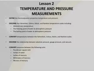
Pressure measurements
Pressure measurements. INTRODUCTION. Absolute pressure = Pgage + Patm. Atmospheric pressure = 100 KP a =14.7 Psi =1 0.2 m H 2 o =760 mm H g =760 torr. Fig. 5.1 Relation between gauge, absolute, and atmospheric pressure. U-TUBE MANOMETER. Fig.5.2. U-tube manometer.

Pressure measurements
E N D
Presentation Transcript
INTRODUCTION • Absolute pressure = Pgage + Patm. • Atmospheric pressure = 100 KPa • =14.7 Psi • =1 0.2 m H2o • =760 mm Hg • =760 torr.
Fig. 5.1 Relation between gauge, absolute, and atmospheric pressure
U-TUBE MANOMETER Fig.5.2. U-tube manometer
The difference between the unknown pressure and the atmospheric pressure is determined as a function of the differential height . Pa- Patm = ρghWhere Pa is the absolute measured pressure, Patm is the atmospheric pressure, ρ is the fluid density
BAROMETER • As shown in Fig. 5.3, The well is exposed to atmosphere pressure. The height h is a measure of the atmospheric pressure. =105Pa
ELECTRICAL PRESSURE TRANSDUCERS • Pressure transducers are devices that convert pressure into an electrical signal. One of its type is "Displacement-type • pressure gauge transducer", shown in Fig. 5.5.
One end of the bourdon tube is fixed. The other end is free to displace. The core of the LVDT is fixed to the free end of the bourdon tube. As pressure is applied to the bourdon tube, the core of the LVDT is pulled through the coil, and an output voltage proportional to the applied pressure is produced, Fig5.6.
5.5.1 Linear Variable Differential Transformer, LVDT Fig.5.7 schematic representation of the LVDT
LVDT consists of one primary coil and two secondary coils within which is placed an iron core. The primary coil is energizes by mean of an alternating current. An induced voltage is produced in the secondary coils by electromagnetic effect. The presence of the iron core enhances this effect. The secondary coils are connected in series opposition, so that when the core is centralized in the coils the produced voltage are equal and opposite. Subsequently the output voltage is zero. When the iron core is displaced from its central or null position, an imbalance in mutual inductance between the primary and secondary coils occurs, and an output voltage is developed proportional to the core displacement.