
Inverse Dynamics
E N D
Presentation Transcript
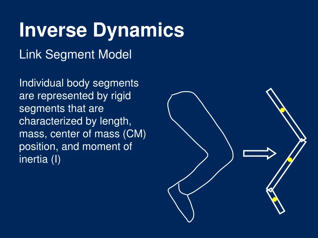
Inverse Dynamics Link Segment Model Individual body segments are represented by rigid segments that are characterized by length, mass, center of mass (CM) position, and moment of inertia (I)
Inverse Dynamics The technique known as “inverse dynamics” involves estimating net forces and net moments (torques) within the musculoskeletal system The “joint reaction forces” are found using Newton’s 2nd Law F = m a The “muscle moments” are also found using Newton’s 2nd Law M = I
Inverse Dynamics Link segment model assumptions • A constant segment mass that can be represented by a point mass at the segment CM • Segment CM locations remain fixed during movement • Adjacent segments are connected by frictionless hinge joints • Segment lengths remain constant during movement • Segment I remains constant during movement
Inverse Dynamics Forces acting on the link segment model • Gravity: downward force, acting at the segment CM, equaling segment mass gravitational acceleration (-9.8 m/s2) • External force: forces measured by a transducer that act at the center of pressure of the distributed force (e.g., ground reaction force center of pressure) • Muscle & ligament force: the net effect of structures that cross the joint, characterized by the net joint (muscle) moment • Joint reaction force: represent the net force that arises between two adjacent segments
Free Body Diagram RYP Sketch of the segment of interest, isolated from the other segments, containing: (1) all force vectors acting on the segment, (2) all moments acting on the segment, & (3) a coordinate system. RXP MP aY a aX mg MD RXD RYD Y X
Free Body Diagram RYP Known variables: ay, ax = segmental acceleration of CM θ = segmental angle in plane of motion α = angular acceleration of segment in plane of motion RXD, RYD =reaction forces at distal end of segment MD =net moment acting at distal end of segment RXP MP aY a aX mg MD RXD RYD Y X
Free Body Diagram RYP Unknown variables: RXP, RYP =reaction forces at proximal end of segment MP =net moment acting at proximal end of segment RXP MP aY a aX • 3 equations allow us to solve for the 3 unknown variables: • FX = maX • FY = maY • M = I mg MD RXD RYD Y X
Free Body Diagram RYP dP RXP MP aY FX = maX RXP + RXD= maX FY = maY RYP + RYD -mg = maY M = I MP- RXP dP(sin ) + RYP dP(cos ) + RXD dD(sin ) − RYD dD(cos ) = I dD a aX mg RXD RYD Y X
A Practice Problem RYP RXD = 60 N RYD = 900 N m = 1 kg ay = -4.21 m/s2 ax = -0.03 m/s2 dD=0.15 m dP=0.12 m θ = 50° α = 36 rad/s2; I = 0.021 kg∙m2 RYP = ?? RYP = ?? MP = ?? dP RXP MP aY dD a aX mg RXD RYD Y X
Inverse Dynamics RYK For a multi-segment system, the analysis begins at the distal segment (e.g., the foot or hand) and proceeds “up the chain” to the more proximal joints Joint reaction forces and net joint moments represent connections between adjacent segments, and are equal and opposite across the joints RXK aYS MK aXS S mgS RXA MA RYA RYA MA RXA aXF aYF GRFX Y F mgF GRFY X
Projection of the GRF Vector Can joint moments during gait be calculated by simply multiplying the resultant GRF vector times the perpendicular distance to each of the relevant joint center? No! This approach has been used, primarily in the clinical arena, but is inappropriate
Joint Moments The output of an inverse dynamics analysis that is typically of the greatest interest is the net joint (muscle) moment d
Joint Moments • Net joint moment includes effects of anatomical structures that produce force across the joint • Away from limits of joint ROM, net moment will be due mostly to muscle activity • Near joint ROM limits there will be a major passive contribution (ligaments, joint capsule) • It is not possible to discriminate individual contributions or muscle co-contraction when evaluating net joint moments • Similarly, the effects of joint friction cannot be partitioned out
Joint Moments - Interpretation Joint moments during the stance phase from three trials in a hip replacement patient The polarity of each moment shows the net moment-producing effect of all muscles acting at that joint The top curve is the sum of the other three, and is called the “support moment”
Joint Moments – Some Applications • Joint moments and serum COMP change due to exercise: https://www.sciencedirect.com/science/article/pii/S0966636215009431?via%3Dihub • Joint moments for chronic ankle instability for jumping and landing: https://insights.ovid.com/pubmed?pmid=28991043
Joint Moments: A few final points • Net joint moments, derived from inverse dynamics, convey the overall goal of the neuromuscular system, and represent the cause of motion of the skeletal system • Net joint moments suffer from indeterminacy; i.e., contribution of different muscles to the net moment cannot be determined • The use of EMG data, in conjunction with inverse dynamics, can help determine individual muscle roles