Download
1 / 20
200 likes | 302 Vues
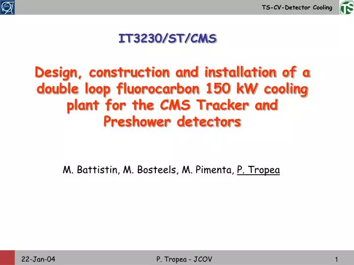
IT3230/ST/CMS. Design, construction and installation of a double loop fluorocarbon 150 kW cooling plant for the CMS Tracker and Preshower detectors. M. Battistin, M. Bosteels, M. Pimenta, P. Tropea. CMS Tracker and Preshower cooling plant General scheme. UXC55. USC55.

E N D
IT3230/ST/CMS Design, construction and installation of a double loop fluorocarbon 150 kW cooling plant for the CMS Tracker and Preshower detectors M. Battistin, M. Bosteels, M. Pimenta, P. Tropea P. Tropea - JCOV
CMS Tracker and Preshower cooling plant General scheme UXC55 USC55 P. Tropea - JCOV
Primary cooling plant functional scheme Chilled water Cooling system: evaporative Fluid: R410A Power: 150 kW Installation: USC55, zone CV R410A to/from UXC55 P. Tropea - JCOV
Primary cooling plant: USC55 zone CV HYDRAULIC EQUIPMENTS • Compressors: 2 or 3, oil free, two stages, piston, regulation system 0÷100% • Condenser: running chilled water and R410A, T_cond= 30°C • Storage tank: equipped with a weight transmitter and a heater • Regulation valve: for chilled water flow rate regulation with respect to thepressure, measured by theptransmitter on the tank • Filter, mechanical • Buffer tank P. Tropea - JCOV
Primary cooling plant: USC55 zone CV ELECTRICAL & CONTROL EQUIPMENTS • Electric power distribution rack for compressors • Electric power distribution rack for detector cooling units (cabling to the UXC55) • Control racks with electronics (PLC) • Control racks for electric/pneumatic signal conversion REQUIRED SERVICES • Compressed air • Electrical power distribution • Chilled water circuit P. Tropea - JCOV
USC55 zone CV P. Tropea - JCOV
USC55 zone CV P. Tropea - JCOV
Electrical and control rack installation Electrical power distribution rack & electrical part of the control racks Control rack: 470 valves for electrical/pneumatic signal conversion 2.5 m 0.9 m 3 & 4 m 0.9 m P. Tropea - JCOV
Piping between USC55 and UXC55 UXC55 USC55 Total pipe length up to first floor balconies, at the service tunnel: 90m “near side” – 120 m “far side” P. Tropea - JCOV
Secondary cooling plants: detector units Fluid: liquid C6F14, cooled by R410A arriving from USC55 7 Cooling Units: 2 x Silicon Strip 1 x Pixel 2 x Thermal Screen 2 x Preshower PERFORMANCES DEMANDED P. Tropea - JCOV
Detector unit layout example: Pixel unit CONTROL RACK for INSTRUMENTATION R410A from/to UXC55 COLD BOX P. Tropea - JCOV
Detector units in the UXC55 HYDRAULIC EQUIPMENTS • Tank: low pressure reservoir, depression created by means of a vacuum pump • Pump: magnetic coupling • Alumina filters: for eventual acids formation • Evaporator:R410A evaporates at -45°C, C6F14 is cooled to the required service temperature (-30°C ÷ -10°C) • Expansion valve: regulates the flow rate of R410A arriving to the evaporator, with respect to the temperature measured at the distribution • Heat exchanger: to sub-cool the liquid R410A • Back pressure regulator: to maintain the distribution pressure constant P. Tropea - JCOV
Thermal Screen and Preshower units: EPS Electrical heater for T regulation Emergency fridge unit (EPS) P. Tropea - JCOV
Detector unit distribution circuits P. Tropea - JCOV
Detector units in the UXC55 DISTRIBUTION LINES HYDRAULIC EQUIPMENTS • Shut-off valve: pneumatic, normally closed shut-off valve, with additional metering screw • Primary element (calibrate orifice): used to measure the flow rate by means of a pressure transducer (shall induce a pressure loss at nominal flow rate of less than 100 mbar) • Small piping for instrumentation (before and after the orifice), equipped with Schrader valves on the control rack • Shut-off valve: pneumatic, normally open • Non-return valve: by-pass for the shut off valve in case of overpressure on the detector circuit P. Tropea - JCOV
Detector units in the UXC55 INSTRUMENTATION on the RACKS • Differential pressure transmitter (piezoelectric): to be connected to the Schrader valves for flow rate measurements • Manometer • Scale transducer REQUIRED SERVICES • Compressed air (valve power) • Electrical power • Waste water recuperation network P. Tropea - JCOV
Detector units overall dimensions Silicon Strip cooling unit Resume for all cooling units P. Tropea - JCOV
Detector units on UXC55 first floor balconies R410A from/to USC55 P. Tropea - JCOV
CMS Tracker and Preshower cooling plant PLANNING IT-3230-TS-CMS out 6 January 04 Bidder’s conference 23 January 04 Tender answers 15 March 04 Finance committee June 04 Contract signature July 04 Design meeting September 04 Complete installation at contractor’s premises February 05 Performance test at contractor’s premises May 05 Cavern installation June 05 Commissioning December 05 P. Tropea - JCOV
CMS Tracker and Preshower cooling plant CONTROL SYSTEM Demanded precision on the set temperature +/- 1 K Demanded maximum overshoot for a step perturbation +/- 3 k ADVANCED CONTROL SYSTEM demanded as an option for each detector cooling unit P. Tropea - JCOV