Download
1 / 82
840 likes | 954 Vues
Explore the principles and applications of Hall effect sensors, essential components for sensing position and measuring magnetic fields in conducting materials, particularly semiconductors. Learn about Hall voltage, Hall coefficient, sensor fabrication, practical considerations, and applications to measure power, rotation, and more.

E N D
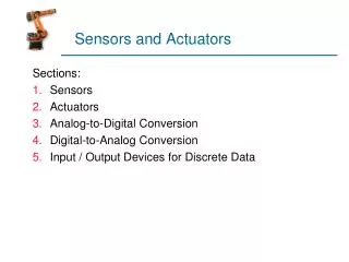
Electric and magnetic sensors and actuators (chapter 5, Part B)
Hall effect sensors • Hall effect was discovered in 1879 by Edward H. Hall • Exists in all conducting materials • Is particularly pronounced and useful in semiconductors. • One of the simplest of all magnetic sensing devices • Used extensively in sensing position and measuring magnetic fields
Hall effect - principles • Consider a block of conducting medium through which a current of electrons is flowing caused by an external field as shown in Figure 5.30. • A magnetic filed B is established across the conductor, perpendicular to the current (. • The electrons flow at a velocity v • A force perpendicular to both the current and field is established.
Hall effect - principles • The electrons are pulled towards the front side surface of the conductor (holes in semiconductors move towards the back) • A voltage develops between the back (positive) and front (negative) surface. This voltage is the Hall voltage and is given by: • d is the thickness of the hall plate, • n is the carrier density [charges/m3] and • q is the charge of the electron [C]
Hall effect - principles • If the current changes direction or the magnetic field changes direction, the polarity of the Hall voltage flips. • The Hall effect sensor is polarity dependent, • may be used to measure direction of a field • or direction of motion if the sensor is properly set up. • The term 1/qn [m3/C] is material dependent and is called the Hall coefficient KH.
Hall coefficient • The hall voltage is usually represented as: • Hall coefficients vary from material to material • Are particularly large in semiconductors. • Hall voltage is linear with respect to the field for given current and dimensions. • Hall coefficient is temperature dependent and this must be compensated if accurate sensing is needed.
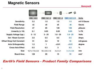
Hall coefficient - cont. • Hall coefficient is rather small - of the order of 50 mV/T • Most sensed fields are smaller than 1 T • The Hall voltage can be as small as a few V • Must in almost all cases be amplified. • Example, the earth’s magnetic field is only about 50 T so that the output is a mere 25 V
Hall effect sensors - practical considerations • Hall voltages are easily measurable quantities • Hall sensors are among the most commonly used sensors for magnetic fields: • simple, linear, very inexpensive, available in arrays • can be integrated within devices. • Errors involved in measurement are mostly due to temperature and variations and the averaging effect of the Hall plate size • These can be compensated by appropriate circuitry or compensating sensors.
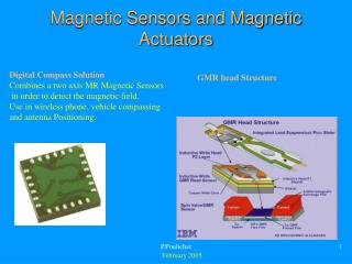
Hall effect sensors - fabrication • A typical sensor will be a rectangular wafer of small thickness • Made of p or n doped semiconductor (InAs and InSb are most commonly used because of their larger carrier densities – hence larger Hall coefficients) • Silicon may also be used with reduced sensitivity) • The sensor is usually identified by the two transverse resistances – the control resistance through which the control current flows and the output resistance across which the Hall voltage develops.
Hall effect sensors - applications • In practical applications, the current is usually kept constant so that the output voltage is proportional to the field. • The sensor may be used to measure field (provided proper compensation can be incorporated) • It may be used as a detector or to operate a switch. • The latter is very common in sensing of rotation which in itself may be used to measure a variety of effect (shaft position, frequency of rotation (rpm), position, differential position, etc.).
Hall effect sensors - applications • Example is shown in Figure 5.31 where the rpm of a shaft is sensed. • Many variations of this basic configuration: for example, measurement of angular displacement. • Sensing of gears (electronic ignition) • Multiple sensors can sense direction as well
Hall effect sensors - applications • Example: measuring power • The magnetic field through the hall element is proportional to the current being measured • The current is proportional to voltage being measured • The Hall voltage is proportional to product of current and voltage - power
Hall elements - specifications • Spec sheet for the TL173C linear Hall effect sensor • Spec sheet for the ATS665LSG digital gear tooth sensor
Magnetoresistive sensors • Two basic principles: • 1. Similar to Hall elements • The same basic structure is used but • No Hall voltage electrodes. (Figure 5.37) • The electrons are affected by the magnetic field as in the hall element • Because of the magnetic force on them, they will flow in an arc.
Magnetoresistive sensors • The larger the magnetic field, the larger the arc radius • Forces electrons to take a longer path • The resistance to their flow increases (exactly the same as if the effective length of the plate were larger). • A relationship between magnetic field and current is established. • The resistance of the device becomes a measure of field.
Magnetoresistive sensors • The relation between field and current is proportional to B2 for most configurations • It is dependent on carrier mobility in the material used (usually a semiconductor). • The exact relationship is rather complicated and depends on the geometry of the device. • We will simply assume that the following holds:
Magnetoresistive sensors • k may be viewed as a calibration function. • A particularly useful configuration for magnetoresistor is shown in Figure 5.37c. • This is called the Corbino disk • has one electrode at the center of the disk • the second is on the perimeter. • This device has the highest sensitivity because of the long spiral paths electrons take in flowing from one electrode to the other.
Magnetoresistive sensors • Magnetoresistors are used in a manner similar to hall elements • Simpler since one does not need to establish a control current. • Measurement of resistance is all that is necessary. • A two terminal device build from the same types of materials as hall elements (InAs and InSb in most cases).
Magnetoresistive sensors • Magnetoresistors are also used where hall elements cannot be used. • One important application is in magnetoresistive read heads where the magnetic field corresponding to recorded data is sensed. • Much more sensitive than hall elements
Magnetoresistive sensors • 2. The second principle: based on the property of some materials to change their resistance in the presence of a magnetic field when a current flows through them. • Unlike the sensors discussed above these are metals with highly anisotropic properties and the effect is due to change of their magnetization direction due to application of the field. • Another name: AMR (anisotropic magnetoresistance)
Magnetoresistive sensors - operation • A magnetoresistive material, is exposed to the magnetic field to be sensed. • A current passes through the magnetoresistive material at the same time. • Magnetic field is applied perpendicular to the current. • The sample has an internal magnetization vector parallel to the flow of current. • When the magnetic field is applied, the internal magnetization changes direction by an angle
Magnetoresistive sensors - operation • The resistance of the sample becomes: • R0 is the resistance without application of the magnetic • R0 is the change in resistance expected from the material used. • Both of these are properties of the material and the construction (for R0). • The angle is again material dependent.
Magnetoresistive sensors - comments • Used exactly like Hall sensors • Much more sensitive • Common in read heads in hard drives • Used for magnetic compasses
Magnetostrictive sensors • The magnetostrictive effect is the contraction or expansion of a material under the influence of the magnetic field and the inverse effects of changes in magnetization due to stress in ferromagnetic materials due to motion of the magnetic walls. • This bi-directional effect between the magnetic and mechanical states of a magnetostrictive material is a transduction capability that is used for both actuation and sensing.
Magnetostrictive sensors • The effect is an inherent property of some materials. • Some materials do not exhibit the effect while others are strongly magnetostrictive. • The effect was first observed in 1842 by Joule (James Prescott Joule 1818-1889). • Has been used very early (1861) for generation of sound and ultrasound. One of the first telephone earpieces was magnetorstrictive.
Magnetostriction • There are two effects and their inverse as follows: • 1.The Joule effect is the change in length of a magnetostrictive sample due to magnetization. • This is the most common of the magnetostrictive effects • Quantified by the magnetostrictive coefficient, , • The magnetostrictive coefficient is the fractional change in length as the magnetization of the material increases from zero to its saturation value. • Its effects are common; the sound emitted by a conventional TV or the humming of a transformer
Magnetostriction • 2.The reciprocal effect to the Joule effect: • The change of the susceptibility (i.e. the permeability of the material changes) of a material when subjected to a mechanical stress, • Called theVillari effect.
Magnetostriction • 3.The twisting of a magnetostrictive sample when an axial field is applied to the sample and a current passes through the magnetostrictive sample itself to create the interaction that causes the twisting effect. • This is known as theWiedemann effectand together with its inverse are used in torque magnetostrictive sensors. • 4.The inverse effect, that of creation of an axial magnetic field by a magnetostrictive material when subjected to a torque is known as theMatteucci effect
Magnetostrictive effect • The magnetostrictive effect is exhibited by the transitional metals including Iron, Cobalt and Nickel and their alloys. • The magnetostrictive coefficients of some magnetostrictive materials are shown in Table 5.3. • There are currently materials that exhibit what is called “giant magnetostriction” in which the magnetostrictive coefficient exceeds 1000 mL/L (Metglass materials and Terfenol-D). • Quickly becoming the materials of choice for magnetostrictive sensors and actuators.
Magnetostriction - uses • Aapplications for magnetostrictive devices • ultrasonic cleaners, • high force linear motors, positioners for adaptive optics, • active vibration or noise control systems, • medical and industrial ultrasonics, pumps, and sonar. • magnetostrictive linear motors, reaction mass actuators, • high cycle accelerated fatigue test stands, • mine detection sensors, hearing aids, • razor blade sharpeners, seismic sources. • Underwater sonar, chemical and material processing.
Magnetostriction - principles • The magnetostrictive effect is quite small • Requires indirect methods for its measurement. • There are however devices which use the effect directly. • The operation of a magnetostrictive device is shown inFigure 5.30.
Magnetostriction - principles • Magnetostrictive devices may be made to sense a variety of quantities. • One of the simplest and most sensitive is to use the magnetostrictive materials as the core of a simple transformer. (discussed later). • Most of the applications of magnetostriction are in actuators. • Sensing can be done by indirect use of the magnetostrictive effect and the Vilari effect
Magnetostriction - position sensing • A cylinder encloses a wire which carries a pulsed current • The current causes a circumferential field in the cylinder. • A magnet encircles the structure causing a local axial field. • The net magnetic field - due to the constant magnetic field of the magnet and the pulsed magnetic field of the wire torques the cylinder
Magnetostrictive position sensor • Local magnetostriction through the Wiedemann effect is generated at the location of the magnet. • This causes a shock wave (ultrasonic wave) • The wave propagates along the cylinder • At the other end, the wave interacts with another magnetostrictive sensor
Magnetostrictive position sensor • The pickup sensor generates a voltage due to the Villari effect (change in strain). • The time it takes for the wave to propagate (from its generation to its pickup) is a measure of the distance from the magnet • The sensor then senses the location of the magnet.