PHOS calibration and alignment
PHOS calibration and alignment. Yuri Kharlov IHEP, Protvino ALICE off-line week 22 February 2005. Outline. Calibration Pre-calibration by wide e - beam Run-time calibration procedures Calibration data structure Alignment Dead/bad channels. Questionnaire.


PHOS calibration and alignment
E N D
Presentation Transcript
PHOS calibration and alignment Yuri Kharlov IHEP, Protvino ALICE off-line week 22 February 2005
Outline • Calibration • Pre-calibration by wide e- beam • Run-time calibration procedures • Calibration data structure • Alignment • Dead/bad channels PHOS calibration/alignment
Questionnaire • General description of objects needed for the detector alignment and calibration • Source of alignment/calibration object - what are the procedures to obtain them. • Approximate size of the objects • Update frequency, validity periods and versioning • Access pattern and access frequency • External DB dependencies PHOS calibration/alignment
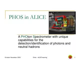
PHOS geometry PHOS has 5 modules Each module consists of EMC and CPV 1 EMC module contains 3584 crystals 1 CPV module contains 7168 pads PHOS calibration/alignment
Calibration data structure AliPHOSEmcCalibrationCoefficient:Float_t fCalibrationCoefficient[nEmc]; // convertion from ADC counts to GeV Float_t fAltroFitParam[2,nEmc]; // two parameters of the signal shape fit TDatetime fTimeStamp; // time stamp when the coefficient was measured AliPHOSCpvCalibrationCoefficient:Float_t fCalibrationCoefficient[nCpv]; // convertion from ADC counts to GeV Float_t fPedestal[nCpv]; // pedestal in ADC counts TDatetime fTimeStamp; // time stamp when the coefficient was measured These classes will contain the methods to set and to get the calibration parameters by the absolute channel number, as well as by the relative channel number (module, row, column). The actual dimensions of arrays fCalibrationCoefficient[nEmc] and fCalibrationCoefficient[nCpv] correspond to the number of crystals in PHOS (nEmc=17920) and the number of pads in CPV (nCpv=35840). PHOS calibration/alignment
Alignment data structure AliPHOSEmcAlignment:Float_t fIp2EmcDistance[5]; // distance from IP to the center of each of 5 EMC modules Float_t fEmcCenterDirection[3,5]; // direction of each of 5 EMC modules seen from IP TMatrixD fEmcOrientation[5]; // Rotation matrix of each of 5 EMC modules in MARS AliPHOSCpvAlignment:Float_t fIp2CpvDistance[5]; // distance from IP to the center of each of 5 CPV modules Float_t fECpvCenterDirection[3,5]; // direction of each of 5 CPV modules seen from IP TMatrixD fCpvOrientation[5]; // Rotation matrix of each of 5 CPV modules in MARS PHOS calibration/alignment
Dead/bad channels AliPHOSBadChannels: Int_t fNEmcBad; // number of EMC bad channels Int_t fNCpvBad; // number of CPV bad channels Int_t fEmcBadChannel(nEmcBad); // Array of EMC bad channel absolute indices Int_t fCpvBadChannel(nCpvBad); // Array of CPV bad channel absolute indices AliPHOSDeadChannels:Int_t fNEmcDead; // number of EMC dead channels Int_t fNCpvDead; // number of CPV dead channels Int_t fEmcDeadChannel(nEmcDead); // Array of EMC dead channel absolute indices Int_t fCpvDeadChannel(nCpvDead); // Array of CPV dead channel absolute indices The classes AliPHOSBadChannels and AliPHOSDeadChannels keep the list of bad and dead channel indices. The array dimensions nEmcBad, nCpvBad, nEmcDead, nCpvDead can be foreseen now as 10% of the total channel number, but real life will correct these dimensions. PHOS calibration/alignment
Source of alignment/calibration objects Sources of calibration/bad-dead/alignment data can be distinguished to initial data and run-time data. • The initial data will be measured in special runs either • in extracted beams before putting PHOS into the pit (calibration coefficient), or • measured via optical survey (initial alignment). • During the run these data will be updated as a result of on-line data analysis. PHOS calibration/alignment
Size of the objects From the object definitions above, the size of the object are as follows: • AliPHOSEmcCalibrationCoefficient: 53,760 32-bit words • AliPHOSCpvCalibrationCoefficient: 107,520 32-bit words • AliPHOSEmcAlignment: 20 32-bit words + 5 Tmatrix • AliPHOSCpvAlignment: 20 32-bit words + 5 Tmatrix • AliPHOSBadChannels: 15,000 16-bit words • AliPHOSDeadChannels: 15,000 16-bit words PHOS calibration/alignment
Update frequency, validity periods and versioning • Calibration data: Depending the actual procedure of run-time calibration, the update frequency will change from 1 day to 1 month. • Alignment constants will be updated once after each mechanical reinstallation of equipment (once per run). • Bad/dead channel tables will be updated in every accelerator technological pause (once in 10 hours?). • Validity period of each constant set is between from one update to another, but all version should be kept in DB for further off-line analysis. • Access frequency is less thanthe update frequency, but not less than 1/day. • External DB dependencies: none. PHOS calibration/alignment
Precalibration by wide e- beam calibration (beam test 2003) PHOS module should be exposed by a wide electron beam at fixed known energy E0 Calibration coefficients ai are found from minimization of the functional Total deposited energy is summed over 5x5 area around the max. cell PHOS calibration/alignment
Energy spectra(beam test 2003) Before calibration Calibration after 3d interation DE/E=3.0% PHOS calibration/alignment
Energy deposition vs (X,Y) (beam test 2003) Before calibration Calibration after 3d iteration PHOS calibration/alignment
Relative calibration coefficients(beam test 2003) after 1st interation after 2d interation after 3d interation Da/a = 0.18% PHOS calibration/alignment
EMC Run-time calibration by p0 mass 200,000 central Pb-Pb events (4 minutes of LHC run) Calibration coefficients can be found by minimization of p0 mass. It requires low combinatorial background high pT longer exposition. pT>5 GeV is a lower limit for this calibration. To calibrate each cell with 1000-event statistics one needs 10 days. PHOS calibration/alignment
EMC run-time calibration by electrons EMC can be calibrated by tracks found by the global tracking procedure and identified as electrons (similar to calibration by e- beam) Where Eiis electron energy in event i. Needed statistics is to be estimated yet. PHOS calibration/alignment
EMC run-time calibration by mean energy PHOS will be polulated by photons distributed uniformly vs X,Y. On average there will be 10 reconstructed photons per module per one central Pb-Pb collision. Mean rec.photon energy can serve as a measure of calibration. To store statistics of 1000 events per channel needed for calibration, one needs 5 minutes of LHC run. PHOS calibration/alignment
CPV run-time calibration by mean charge CPV responds to charged particles passing through CPV gas volume. On average there will be 100 charged particles per module per one central Pb-Pb collision. Similar to PHOS EMC, CPV fired pads will be distributed uniformly vs X,Y. Pad response function (induced charged) can serve as a measure of calibration. To store statistics of 1000 events per pad needed for calibration, one needs <1 minute of LHC run. PHOS calibration/alignment
Conclusion • PHOS calibration/alignment is still at the level of ideas based on experience of other experiments and on PHOS test beams. • Pre-calibration of PHOS by wide electron beam is a routine procedure well elaborated in PHOS code for test beams, and should be adapted to real DAQ. • Implementation of run-time calibration procedures is to be written yet. • Alignment data is not used yet in PHOS. The geometry definition should be changed to incorporate alignment constants. PHOS calibration/alignment