Download
1 / 15
150 likes | 170 Vues
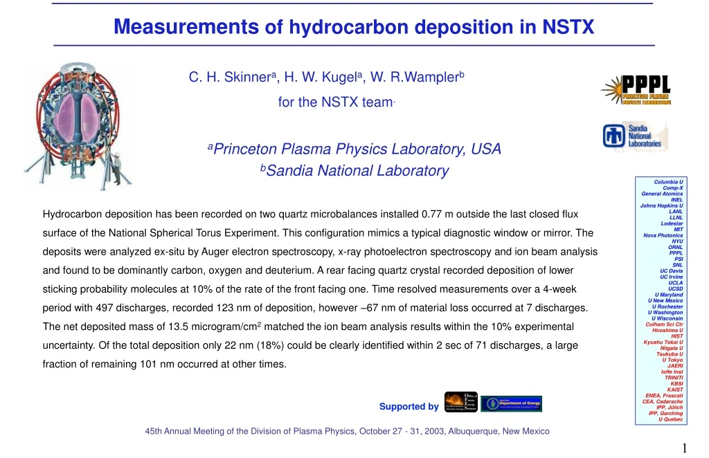
Supported by. Measurements of hydrocarbon deposition in NSTX. C. H. Skinner a , H. W. Kugel a , W. R.Wampler b for the NSTX team. a Princeton Plasma Physics Laboratory, USA b Sandia National Laboratory. Columbia U Comp-X General Atomics INEL Johns Hopkins U LANL LLNL Lodestar MIT

E N D
Supported by Measurements of hydrocarbon deposition in NSTX C. H. Skinnera, H. W. Kugela, W. R.Wamplerb for the NSTX team. aPrinceton Plasma Physics Laboratory, USA bSandia National Laboratory Columbia U Comp-X General Atomics INEL Johns Hopkins U LANL LLNL Lodestar MIT Nova Photonics NYU ORNL PPPL PSI SNL UC Davis UC Irvine UCLA UCSD U Maryland U New Mexico U Rochester U Washington U Wisconsin Culham Sci Ctr Hiroshima U HIST Kyushu Tokai U Niigata U Tsukuba U U Tokyo JAERI Ioffe Inst TRINITI KBSI KAIST ENEA, Frascati CEA, Cadarache IPP, Jülich IPP, Garching U Quebec Hydrocarbon deposition has been recorded on two quartz microbalances installed 0.77 m outside the last closed flux surface of the National Spherical Torus Experiment. This configuration mimics a typical diagnostic window or mirror. The deposits were analyzed ex-situ by Auger electron spectroscopy, x-ray photoelectron spectroscopy and ion beam analysis and found to be dominantly carbon, oxygen and deuterium. A rear facing quartz crystal recorded deposition of lower sticking probability molecules at 10% of the rate of the front facing one. Time resolved measurements over a 4-week period with 497 discharges, recorded 123 nm of deposition, however –67 nm of material loss occurred at 7 discharges. The net deposited mass of 13.5 microgram/cm2 matched the ion beam analysis results within the 10% experimental uncertainty. Of the total deposition only 22 nm (18%) could be clearly identified within 2 sec of 71 discharges, a large fraction of remaining 101 nm occurred at other times. 45th Annual Meeting of the Division of Plasma Physics, October 27 - 31, 2003, Albuquerque, New Mexico
Motivation: Deposition on TFTR graphite tile 50 microns • Deposition in next step devices will scale up two orders-of-magnitude with pulse length (bigger change than plasma parameters). • Codeposition of tritium with carbon will prevent use of carbon PFCs in ITER unless credible tritium removal techniques are demonstrated on tokamaks. • Deposition is serious threat to survival of first mirrors. • Recycling behaviour will change in areas of net deposition. • Condition of plasma facing surfaces generally remains hidden and undiagnosed. S Willms and W Reisiwig LANL Deposition on mirrors Experimentally measured solid points and calculated lines with corresponding open markers spectral dependencies of effective reflectance for clean SS and for SS with carbon coating of thickness shown on each curve. Voitsenya et al., Rev. Sci. Instrum. 72 (2001) 480.
NSTX Deposition on Wall Coupons gas injectors Deposition from plasma operations September 2000 to August 2001 including 9 boronizations • Factor of 5 Variation in Deposition Toroidally• Factor of 6 to 9 Variation in Deposition Poloidally
NSTX Deposition Monitor • Principle: quartz crystal oscillates at ~ 6 MHz, exact frequency depends on mass and on temperature - not affected by EMI . • Deposition inferred from change in frequency (measured to ~1Å, ~1Hz) • Detector is located in 4” tube outside main plasma chamber ~ 77 cm from last closed flux surface • Detector configuration mimics typical diagnostic windows and mirrors, - samples neutrals deposited on NSTX wall away from plasma. • Gate valve permits sample retrieval for surface analysis without machine vent • Data obtained January/February ‘03.
Installation on NSTX Plasma facing crystal detector inside Shutter Si coupon Backward facing crystal Bay K Thermo- couples plasma -> 4” Gate Valve oscillator crystal @ R= 231 cm ~ 77 cm from last closed flux surface 33 cm below midplane Dep Mon + T/C Signals, water cooling, air for shutter
Quartz crystal microbalance • Infincon XTM/2 with bakable crystal • Specification: • Detector resolution ≈1 Å (≈ one monolayer). • Accuracy 0.5% • Bakeable to 450°C - water cooled during deposition monitoring. • Built in shutter on plasma facing detector. • Thermocouples on both detectors record temperature. Si witness coupon Rear facing crystal Gold coated quartz crystal Thermocouple Shutter (folded back) Realtime readout Gold coated quartz crystal
Ex-situ Surface Analysis Auger electron energy unique to each element SEM: scanning electron microscopy AES: Auger electron spectroscopy Atomic concentration of elements in percent (excluding hydrogen isotopes and helium) normalized to 100% as measured by x-ray photoelectron spectroscopy. internal relaxation secondary electron ejected incident 10 keV electron Inelastically scattered electron 3 keV Ar+ beam sputters surface to give depth profile. XPS: X-ray photoelectron spectroscopy photo electron energy related to binding energy unique to each element x-ray Analysis by Note: AES, XPS does not detect hydrogen or helium. Quartz #5 front facing Ion beam analysis Carbon density from proton scattering; incident 1.7 MeV proton Deuterium density from d(3He,p)4He nuclear reaction incident 0.7 MeV 3He
Deposition on forward & backward facing crystals Plasma facing quartz crystal XPS elemental analysis SEM Carbon AES shows depth of layer to be 400 Å (assuming sputter rate same as diamond-like carbon.) XPS shows the surface of the samples contained mostly carbon (as C-(C,H) and C-O) and oxygen. Quartz Xtal 5 (plasma facing) also contained boron (as B3+ and possibly B-N) and nitrogen (as C-N and NOx). Counts Oxygen Binding Energy (eV) Back facing quartz crystal XPS elemental analysis SEM AES shows depth of layer to be 45 Å (assuming sputter rate same as diamond-like carbon.) The surface contained mostly carbon (as C-(C,H) and C-O) and oxygen also contained nitrogen (as C-N and R4-N+) and gold (as Au°). The general lineshape indicates the presence of an overlayer on a gold substrate. The lineshape to the left of the carbon peak indicates that carbon is in this overlayer. Difference between plasma facing and backward facing deposition related to sticking coefficients. Carbon Oxygen Counts Binding Energy (eV) Analysis by
Ion beam analysis matches microbalance Comparison of mass of deuterium and carbon in deposits measured by Ion Beam Analysis (IBA), and total mass measured by quartz microbalance of samples exposed to plasma discharges. D/C ratio = 0.1 Quartz #5 front facing 13.5 13.3 The thickness is based on an assumed density of 1.6 g/cm3. Excellent agreement between mass measured by proton scattering and by microbalance
Time resolved deposition Deposition over period January 10th - February 14th 2003 Deposition over three hours, discharges 110150 - 110165 110156 for density = 1.6 g/cm3 110155 No detailed correlation of enhanced deposition with diagnosed plasma parameters
Similar discharges - different deposition Most discharges show low but cumulative deposition Stored Energy, RF power, Strike point position, Outer gap, tile temperature and gas pressure etc... very similar. Angstrom Seconds Some very similar discharges showed high deposition Angstrom Outer Strike Point Position Pressure (torr) Seconds
Material loss on some discharges 109987 109988 109987 (no loss) 109988 (loss) 109994 109988 (no loss) Material loss over discharges 109988 - 109993 seconds Decrease at t= 2 seconds after the initiation of the discharge.
Material loss on some discharges 109988 (with material loss) 109987, 109994 (without loss). Pressure (torr) Outer Strike Point Position No clear correlation to stored energy, NB power, strike point position, outer gap, tile temperature and gas pressure etc...
Deposition after discharge 110106 Delayed deposition following CHI discharge 109588. Sequence of small increments of deposition, most (but not all) occur 2-30 s after discharges 110106 – 110118 shown by P. Step rises in deposition not coincident with a discharge appear to be due small temperature rises. seconds Delayed deposition
Summary • NSTX shows net deposition on wall, heaviest at midplane and near gas injectors • Quartz microbalance measured deposition 77 cm from plasma in diagnostic mirror-like geometry. • 29 µg/cm2 deposition accumulated over 4 weeks and 497 discharges with 16 µg/cm2 material loss over 7 discharges. • Deposited layers are mostly carbon with some oxygen and deuterium. • Deposition recorded on surface facing away from plasma from low sticking probability radicals at 10% rate of plasma facing surface. • Mass of deposited layer independently confirmed by ion beam analysis. • No detailed correlation of higher deposition discharges or material loss with diagnosed plasma parameters. • Indications that about only half of deposition occurs promptly after discharges. • Evaporation of polymer-like films between discharges has been previously postulated[1]. • If confirmed this has important consequences for tritium retention and strongly supports use of shutters to minimise exposure of diagnostic first windows and mirrors. [1] A. von Keudell, C. Hopf, T. Schwarz-Selinger, W. Jacob, Nucl. Fus, 39 (1999) 1451. suggested a potential mechanism for deposition: “It is also conceivable that, due to the relatively high surface temperature in JET (>500K), polymer-like films produced during plasma interaction evaporate after each discharge and are deposited on the cold louvers in pulse pauses as well.”