Download
1 / 45
450 likes | 582 Vues
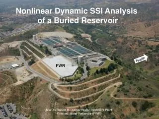
Nonlinear Dynamic SSI Analysis of a Buried Reservoir. North. FWR. MWD’s Robert B. Diemer Water Treatment Plant Finished Water Reservoir (FWR). EWWT. North. A. Shear wall. Shear wall. B’. B. A. 20 ft. Ravine. 720 ft. FWR, Plot Plan & Section B-B’. Design Earthquakes.

E N D
Nonlinear Dynamic SSI Analysis of a Buried Reservoir North FWR MWD’s Robert B. Diemer Water Treatment Plant Finished Water Reservoir (FWR)
EWWT North A Shear wall Shear wall B’ B A 20 ft Ravine 720 ft FWR, Plot Plan & Section B-B’
Design Earthquakes • MCE - M6.8 event on Wittier Fault, PGA=1.17 g • Landers, Superstition Hills, and Kobe records • Spectrally matched to design response spectrum:
Design Horizontal Acceleration Histories FWR, Diemer Plant Figure 4
FWR - North Wall East Wash Water Tank Section A Finished Water Reservoir FWR, Diemer Plant
FWR - North Wall Section A East Wash Water Tank Foundation • After 1971 S.F. EQ: • Removal of • 3 ft of earth cover • from roof • Excavation behind • North Wall (up-slope) • And addition of a • separate retaining wall swale FWR, Diemer Plant
Objectives • Investigate probable cause of horizontal cracking observed inside the reservoir at roughly mid-height of the north wall • Explore sensitivityto pre-shaking earth pressure behind wall • Evaluate seismic performance for MCE shaking Analysis Approach • 2D time domain, nonlinear dynamic SSI analyses with FLAC • Soil & bedrock simulated with elasto-plastic Mohr-Coulomb model • Reservoir, retaining walls, and bypass pipeline modeled with elasto-plastic beam elements which develop plastic hinges • Hydrostatic pressures applied to reservoir wall and bottom slab • Hydrodynamic forces of reservoir water approximated with Westergaard added mass
FWR North Wall - Section A South North Fill “Free-Field” Boundary “Free-Field” Boundary Bedrock Non-reflective boundary • Interface elements between soil and beam elements • Stiffness of two N-S shear walls simulated by rigidly linking horizontal displacements of roof and floor slabs.
Structural Properties – North Wall * Cracked section (ACI, 2005) ** Distributed over 10-ft wide force trajectory for 20-ft column spacing
Analysis Sequence with Model Calibration Based on Measured Wall Deflections • Original Structure • Fully buried • Empty reservoir • Econcrete = 82%*Einitial • Icreep = 22%*Iuncracked • Full reservoir (809.25 ft) 815 810 805 800 Elevation (ft) 795 790 • Existing Structure • Full reservoir • Excavate + retaining wall • Econcrete = 100%*Einitial • Ieff = 50%*Iuncracked • Empty reservoir Ko = 0.7 produced “target” wall deflection = 21 mm Full reservoir • Static equilibrium • EQ shaking 785 780 815 810 805 Existing: ~21 mm deflection 800 Elevation (ft) 795 790 785 780 FWR, Diemer Plant Figure 10
B e f o r e E x c a v a t i o n A f t e r E x c a v a t i o n 814 814 F W R R o o f F W R R o o f 812 812 810 810 808 808 806 806 ) 804 t 804 f ( K = 0 . 7 n o o i 802 t 802 a v T o t a l F o r c e 35 k i p s / f t e l E 800 800 l l a W 798 R 798 W F 796 796 794 794 792 792 790 790 F W R B o t t o m S l a b F W R B o t t o m S l a b 788 788 786 786 0 1 2 3 4 5 6 7 8 9 0 1 2 3 4 5 6 7 8 9 P r e s s u r e ( k s f ) P r e s s u r e ( k s f ) Earth-Pressure Distributions (Section A1) FWR, Diemer Plant
Static-Moment Distribution (Section A1) Original, fully buried FWR structure “Before Excavation” 41.6 kip*ft/ft Moment initiating concrete cracking= 18.3 kip*ft/ft “After Excavation” (Following 1971 S.F. EQ) 38.5 kip*ft/ft FWR, Diemer Plant
B e f o r e E Q A f t e r E Q A FWR S w a l e S w a l e FWR K = 0 . 5 o l l 1 . 0 a 2 . 0 W R W F F W R S l a b F W R S l a b 0 4 8 0 4 8 P P r r e e s s s s u u r r e e ( ( k k s s f f ) ) Earth Pressure Distribution before and after EQ for Varying K0 swale
) t f / s A p i FWR k ( e c Swale r o F l a i x A ) g ( . l e c c A Probable Cause of Horizontal Cracking Axial-Force History in Swale for 0.25 PGA EQ 8 FWR 4 Shaking-induced Axial Force In Swale 0 0.3 M 4.6 Whittier Narrows, 1987 0.0 -0.3 0 5 10 15 20 25 30 T i m e ( s e c o n d s )
60 A FWR k o = 2 . 0 FWR k o = 1 .0 . 30 ) t f / s Shaking-induced soil force against FWR p i k ( k o = 0 . 5 e c r 0 o F l 1.2 a t Input acc. history o T 0.0 -1.2 0 5 10 15 20 25 30 T i m e ( s e c o n d s ) ) g ( . l e c c A Effect of Pre-EQ Ko on Shaking-Induced Soil Force swale
0 1.1 ft ) . n i ( . -1 c Plastic rotation 0.025 Rads e l f e D -2 I n i t i a l K = 0 . 7 o 1.2 ) g L a n d e r s ( 0.0 . c c -1.2 A 0 10 20 30 T i m e ( s e c o n d s ) Deformed Mesh and Wall Deflection History: MCE Shaking MCE - FWR North Wall - Post-shaking permanent deformations FWR North Wall – Deflection history
) t 80 f / t f . 1 k i p f t / f t = 4 . 4 5 k N m / m s . . W a l l p i 40 k ( t n e 0 m F l o o r o M -40 n o 1.2 ) i t n a a W a l l R e s e r v o i r t i o d h i n g e s R a 0.0 r c i % t s F l o o r ( a l P -1.2 1.2 ) g L a n d e r s ( . c 0.0 c A -1.2 0 5 10 15 20 25 30 T i m e ( s e c o n d s ) Moment & Plastic Rotation Histories at Wall and Floor
Summary of Permanent Plastic Hinge Rotations for All Earthquakes (Initial runs for determining governing EQ) FWR, Diemer Plant
North wall South wall South Wall Analyses North MWD’s Robert B. Diemer Water Treatment Plant Finished Water Reservoir (FWR)
Diemer FWR – South Slope 20 caissons (10 ft o.c.) 12 caissons (10 ft o.c.) Section B Section A
Diemer FWR – South Slope Soil Properties *) Shear-wave velocity (Vs)derived from downhole geophysical surveys
Top Soil (Colluvium) Diemer FWR – South Slope Static F.S.= 1.23 Yield acceleration = 0.06g Shaking-induced deformation = 5.5 ft (MCE) FWR Fill Topsoil (Colluvium) Bedrock
Diemer FWR – South Slope Static F.S.= 1.34 Yield acceleration = 0.08g Shaking-induced deformation = 4.8 ft (MCE) FWR Fill Bedrock Topsoil / Slope Wash
Wall top ~0.7ft Reservoir ~0.3ft 60 ft 10 ft 10 ft FWR South Slope Section A Buttress Wall Initial Objective: Stabilize the “soil wedge” beneath the reservoir
Panel top ~0.1ft Reservoir ~0.1ft 55 ft 30 ft FWR South Slope Section A Shear Panels 30 ft Initial Objective: Stabilize the “soil wedge” beneath the reservoir 10 ft 10 ft
Wall top <0.1 ft Reservoir <0.1 ft 40 ft FWR South Slope Section A Diaphragm Wall anchored into Reservoir Floor and/or Shear Walls Initial Objective: Stabilize the “soil wedge” beneath the reservoir
FWR - South Wall Analysis Fill Colluvium Weathered Bedrock Bedrock SECTION A1 - SOUTH In the ravines the reservoir is supported by caissons to bedrock • N-S shear walls simulated by horizontally linking roof and floor slabs. • Soil & bedrock >>> elasto-plastic Mohr-Coulomb model • Reservoir & caissons >>> elasto-plastic beam elementss • Hydrostatic pressures applied to reservoir wall and bottom slab • Hydrodynamic forces approximated with Westergaard added mass
Structural Properties – South Wall *) Cracked section (ACI, 2005) **) Distributed over 10-ft wide force trajectory for 20-ft column spacing ***) Actual wall-beam properties (i.e. not distributed per ft)
South Slope Displacement Vectors After Earthquake, Section A Max displacement ~2 in
South Wall Deformations After Earthquake, Section A Exaggerated 100 times ~ 2 in
M o m e n t a n d S h e a r F o r c e H i s t o r y o f C a i s s o n D u r i n g E a r t h q u a k e s ) t . f . y i e l d m o m e n t ( 3 9 . 5 k i p f t ) p i k ( t n e m o M 30 ) p i k ( e c r o F r a e h S ) g ( n o i t a r e l e c c A FWR 100 70 40 10 -20 . -50 y i e l d m o m e n t ( - 3 9 . 5 k i p f t ) -80 0 5 10 15 20 25 t i m e ( s e c o n d s ) 30 s h e a r c a p a c i t y ( 1 9 . 6 k i p ) 20 10 0 -10 s h e a r c a p a c i t y ( - 1 9 . 6 k i p ) -20 -30 0 5 10 15 20 25 30 t i m e ( s e c o n d s ) 1.2 Input L a n d e r s / L u c e r n e S t a t i o n , 2 7 5 C o m p . 0.6 0.0 -0.6 -1.2 0 5 10 15 20 25 30 t i m e ( s e c o n d s )
Deflected wall beam 0.06” Spring4 Spring3 Spring2 Spring1 A2 A1 Structure Deformations (Landers EQ, Normal Polarity) Section A1, Exaggerated 5x Plastic Rotation @ Caisson Head: >5% Plastic Rotation @ Mid of Caisson: >5% Max. Caisson Deflection: 12.0 in Section A2, Exaggerated 5x Plastic Rotation @ Caisson Head: <0.1% Plastic Rotation @ Mid of Caisson: 0% Max. Caisson Deflection: 0.1 in South Wall, Exaggerated 2,000 x FWR, Diemer Plant
4 3 2 1 A2 A1 Compression Tension Section A1 History of Caisson Axial Force Caisson is “hanging” on the South-Wall beam FWR, Diemer Plant
4 3 2 1 A2 A1 Section A2 History of Caisson Axial Force Compression FWR, Diemer Plant
4 3 2 1 A2 A1 History of Spring 1 Axial Force Compression FWR, Diemer Plant
4 3 2 1 A2 A1 History of Spring 2 Axial Force Compression FWR, Diemer Plant
4 3 2 1 A2 A1 History of Spring 2 Axial Force Compression FWR, Diemer Plant
Reservoir Wall Moment after Landers EQ (Section A1) 363 kip*ft 834 kip*ft Max. = 834 kip*ft FWR, Diemer Plant
Reservoir Wall-Beam Moment History Note: Moment history recorded at wall-beam element to the right of Caisson A1 - in the axis of the canyon FWR, Diemer Plant
80 ) t f 40 . p i k ( t 0 n e m o -40 M -80 0 5 10 15 20 25 30 t i m e ( s e c o n d s ) 0.010 0.010 ) d a r ( h i n g e l o c a t i o n n o i t R e s e r v o i r a t 0.005 0.005 o R c i t s a l P 0.000 0.000 0 5 10 15 20 25 30 t i m e ( s e c o n d s ) 1.2 1.2 ) g 0.6 0.6 ( n o i t a 0.0 0.0 r e l e c c -0.6 -0.6 A -1.2 -1.2 0 5 10 15 20 25 30 t i m e ( s e c o n d s ) Section A1 - Reservoir Roof Moment &Plastic Rotation 80 yield moment = 66 kips.ft 40 0 -40 yield moment = -66 kips.ft -80 L a n d e r s / L u c e r n e S t a t i o n , 2 7 5 d e g FWR, Diemer Plant
Study Conclusions • Performance Criterion: Prevention of structural collapse which would result in uncontrolled release of water from the reservoir • FEMA 356 allows up to 0.02 radians of plastic rotation for “collapse prevention” level of performance of primary structural members • Plastic rotations are less than 0.02 radians for all sections analyzed • Finished Water Reservoir structure was concluded to be seismically stable for MCE shaking