Coastal Glider Overview
Coastal Glider Overview. Oceanology International -- March 2014. Outline. Underwater Gliders The Coastal Glider [CG] Specifications Sensors Deployment Successes Deployment Vessels. Some Background. Legacy Gliders

Coastal Glider Overview
E N D
Presentation Transcript
Coastal Glider Overview Oceanology International -- March 2014
Outline • Underwater Gliders • The Coastal Glider [CG] • Specifications • Sensors • Deployment Successes • Deployment Vessels
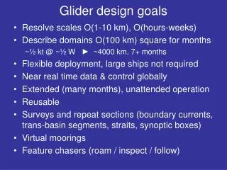
Some Background • Legacy Gliders • Developed for measuring oceanographic properties in the open ocean at low costs • Unmanned robotic vehicle with a sensor suite to collect oceanographic parameters of interest • Low power and slow moving but very efficient glide patterns to increase life times in deep ocean basins • Alaska Native Technologies [ANT] developed the Littoral Glider for coastal military/environmental applications with funding from ONR • Developed glider with larger payload and speed capability • Overcomes many of the shortcomings of the legacy gliders • Exocetus [x-o-seat-us] Development LLC formed in May 2012 and purchased all the assets and intellectual properties of ANT on 9 Oct 2012 • Manufacturing facility in Anchorage, AK • Markets are scientific/research, oil & gas and military
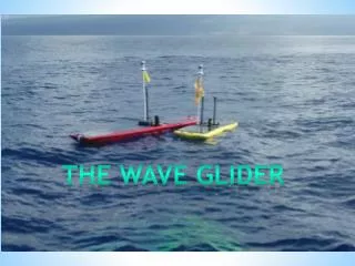
Underwater Glider Operation No external moving partsneeded to control glider,control managed throughchanges in position of aninternal mass Energy only needed at top and bottom of each ‘yo’ to change buoyancy Wings provide forward motion during sinking and floating
Why Gliders? • Gliders are truly transformational • Low Power • Buoyancy changes drive vehicle up / down • Wings provide lift to drive forward • Hence, long endurance per small size • Autonomous • Proven command, control and navigation even in bad weather through GPS, Iridium link in one antenna • Control through internet • Small • Two-person deployable • Platform independent (Catacraft size to Research Vessel) • Inexpensive, $180K to $230K, depending on sensor package
Outline • Underwater Gliders • The Coastal Glider • Specifications • Sensors • Deployment Successes • Deployment Vessels
CG Is Superior To Legacy Gliders-- In Coastal Waters • Adaptive Ballasting • CG can operate from fresh to salt water without manual re-ballasting (10 – 37 ppt) • CG can operate in estuary environments • Speed Requirements • CG has a commanded speed range from 0.7 to 2.0 knots • Environmental Parameters • CG can operate in water depths as shallow as 3 m (w/ reduced navigational and speed capabilities) • Performance • CG has greater space and power for installing many sensors
Glider Major Systems/Subsystems • Buoyancy Engine (BE) • Pitch/Roll System • Control System • Communications System (in EB) • Power System
Coastal Glider Components Altimeter Hull Assembly ElectronicsBay Assembly Tail SectionAssembly Roll Cage Assembly Seal Kit Main Board Main Board CTD Sensor BatteryPack Pitch and RollAssembly BuoyancyEngine
Coastal Glider Functional Analysis • What does a glider do? • Receives a Mission • Executes that Mission • Launch • Transit/Maneuver/Navigate • Collect/Store Data • Transmit Data • Keeps itself safe • Ends Mission (Recovery)
CG Comms Navigation Processor WIFI/ 802.11 Communications Buoyancy Engine BE Pump Iridium SatComs BE Valve Guidance Navigation & Vehicle Control SW Freewave LOS Science Computer Sensor Processing BE Meas. GPS Lift Bag Stamp Processor Lift Bag User Selected Sensors Functional Block Diagram Pitch System Roll System Data Storage Navigation Sensors Altimeter IMU Depth Power Converters Batt. V&I Internal T&P Ultra-Capacitors Main Battery
Outline • Underwater Gliders • The Coastal Glider [CG] • Specifications • Available Sensors • Deployment Successes • Deployment Vessels
Coastal Glider Operational Capabilities • Heading Maneuver (Heading, Speed, Time) • Waypoint Maneuver (Waypoint, Arrival Time) • Communications Maneuver (Surface, Nose Down) • Station-Keeping Maneuver (Waypoint, Radius) • Drift/Reposition Maneuver (Waypoint, Radius) • Surface Maneuver (Recovery Mode) • Hover Maneuver (Depth, Depth Tolerance, Time) • Loiter Maneuver (Radius, Time) • Sleep Maneuver (Time) • Emergency Rise Maneuver (Depth, Heading) • Emergency Dive Maneuver (Depth, Heading)
Duration Vs Power 3.85 kWatt-hrs – Alkaline 14.1 kWatt-hrs – Lithium Fly Hover Spar 40 days hover - Alkaline 18 days flight - Alkaline
Battery Specifications • Alkaline Primary • 462 ‘C’ cells in 18s/2p configuration • 33 VDC nominal; 18 VDC Cut-off • 3,850 W-hrs (14 mJ) • ~70 lbs (~32 kg) • Lithium Primary • 342 ‘D’ cells in 12s/3p configuration • 32 VDC nominal; 18 VDC Cut-off • 14,100 W-hrs (67 mJ) • ~70 lbs (~32 kg) • Rechargeable Lithium Ion [underdevelopment] • 735 “18650” cells in 7s/15p configuration • 30 VDC nominal with 18 VDC cutoff • 8,200 W-hrs (29.5mJ) • ~70 lbs (~32 kg)
Buoyancy Engine [BE] Design • BE designed to have a range of 0 to 6.25 inches of travel (approx. 5 L; 11.7 lbs) • 5L is 4.7% of CG mass • Legacy gliders have approx 0.5 L or less than 1% of vehicle mass • Designed maximum speed requires +/- 3.2 lbs (6.4 lbs total) and a glide slope of 35 degrees • Remaining 5.3 lbs ‘reserved’ for adaptive ballasting (range of 27 ppt) • Reserve can be used for speed if full adaptive ballasting is not necessary
Hydraulic System Schematic BE Ingest Valve (O) “Accumulator” Filter Pump (Off)
Hydraulic System Schematic BE Expel “Accumulator” Valve (C) Filter Pump (On)
CG BE Overview • The CG BE is both Variable and Adaptive: • Variable aspects allows for variable speed: • The amount the glider ingests and expels at each deflection is determined by the commanded speed • Larger commanded speeds result in larger BE displacements and therefore larger changes to the net buoyancy • Larger displacement require the BE to run longer and result in higher BE duty cycles • Adaptive aspect allows the LG to self-ballast: • As water density changes, the glider adjusts the ‘Neutral Buoyancy Position’ (NBP) of the BE • This is done continuously • The result is a low duty cycle adjustment to the BE during ascent/descent • Added drag on the glider (e.g. from a tethered modem) ‘looks like’ density variations and result in BE adjustments during ascent/descent
BE Adaptive Speed 0.0 inch BE Range 6.25 inch 1 knot @ 1019 kg/m^3 1.8 in 3.9 in 2 knot @ 1019 kg/m^3 1.1 in 4.6 in
BE Adaptive Ballasting 0.0 inch BE Range 6.25 inch 1 knot @ 1027 kg/m^3 0.7 in 2.8 in 1 knot @ 1010 kg/m^3 3.0 in 5.1 in
CG Spider Plot Optimum Speed 15.0°
Electronics Bay (EB) Electronics Bay: EB • Sensors integrated with other electronics and deployed as a single unit in EB • Reduced deployment risk, increased reliability • Six-liter volume available in EB for payloads (acoustics, mission specific electronics boards, etc.) CTD Sensor 6 L Space Available Comms Board EB External EB Internal
Electronics Bay Specifications • 7.5” ID x 12” length standard (~80% or 420 inʌ3 dry volume available for sensor integration) – Length can be extended • 19.1 cm ID x 30.5 cm length standard (~80% or 7 L dry volume available for sensor integration) • 12 VDC (3 amp max) power available via GPIO switch • 5 VDC, and 3.5 VDC power available via expansion board • 18 - 33 VDC unregulated raw battery power is available • 5 Kg (11 lb) nominal payload capacity • Note: Additional payload capacity can be added by including syntactic foam in flooded areas (fore and/or aft) • Plug plane separation from CG body eases payload swapping
Hull Penetrations • The CG has (6) standard hull penetrations for sensor integration: • 0.625 Dia Thru holes w/ 1.250 Dia Spot face. • Sized for a SubConn Standard Circular series bulkhead connector (6 – 12 contacts; e.g. BH10F connector) • Two penetrations are in the bow of the glider, above the BE, in the flooded nose cone: • One of these is utilized for the altimeter and the BE safety magnetic interlock; • The other is plugged. • Four penetrations are in the stern of the glider, around the flange of the Electronic Bay: • These access the flooded tail cowling section; • One is used for the CTD/SVTP (if present); • One is used for the Emergency Lift Bag system; • Two are available and plugged.
Outline • Underwater Gliders • The Coastal Glider • Specifications • Sensors • Deployment Successes • Deployment Vessels
Coastal Glider Sensors -- Integrated to date • SeaBird GPCTD [aft cowling] • RINKO Dissolved Oxygen [bow] • WET Labs ECO FLNTU [bow] • AML Micro CTD [stern] • Ocean Sonics HF Smart Hydrophone [wings and vertical stern plane] • Wilcoxon Vector Sensor VS-301 hydrophone [bow Narwhal] • Reson TC-4033 [wings and vertical stern plane]
RINKO-II Hypoxia Sensors Measurement Specifications Parameter Dissolved Oxygen Sensor Temperature Sensor Measurement principle Phosphorescence lifetime Thermistor (optode) Response time 0.4 sec (63%) 0.2 sec 0.9 sec (90%) Range 0 to 200%(0 to 20 mg/L) ‐5 to45°C Resolution 0.01 to0.4%(2to8 μg/L) 0.001 °C Accuracy ) ± 2% (at 1 atmosphere, 25 °C ) ± 0.02 °C Stability ±1% (24 hours) ±5% (1 month)
Hypoxia Sensors Placement Place both sensors in nose cone, extending the nose cone by 6 inches
SeaBird GPCTD Sensor Measure Calibration Accuracy Accuracy Resolution Range Range (within cal range) (outside range) Conductivity (S/m): 0 to 9 0 to 6 ± 0.0003 better than ±0.0010 0.00001 (mS/cm) (0 to 90) (0 to 60) (± 0.003) (±0.010) (0.0001) Temperature (°C): -5 to +42 +1 to +32 ± 0.002 better than ±0.004 0.001 Pressure (depth) (dbar): 0 to 350 full scale ± 0.1% F.S. -- 0.002% F.S. • Memory • 8 Mbytes = 699,000 of CTP (194 hours at 1 Hz) • Data Formats • Real-time data and uploaded data are output (decimal or Hexadecimal characters) in units of Siemens/meter (conductivity), degrees C (temperature), decibars (pressure) • Operating Power Requirements • Supply Voltage: 8 to 20 VDC nominal (power calculations below assume 10.0 V) • Quiescent current: 30 μA • Continuous (1Hz) Sampling • CTP only: 175 mW if real-time = no, 190 mW if real-time = yes (2.10 – 2.28 Watt-hours/day @ 50% duty)
Coastal Glider Hydrophones • Ocean Sonics icListen HF Hydrophones on wings and stern plane • Measures ambient noise in1/3 octave bands • Fishing vessels and ferries • For wind speed estimator • Provides event detection • Mammals, sea turtles and fish • Vessel engine tonals • Wilcoxon Vector Sensor VS-209 hydrophone on bow Narwhal • Measures direction of surface vessels • Measures direction of wind waves and swells • Provides detection and direction of marine mammals
Ocean Sonics Smart Hydrophone • Analog hydrophone needs many parts, but Smart Hydrophone is Complete • All functions are integrated • Unit is calibrated
Ocean Sonics icListen HF Smart Hydrophones • Hydrophone Sensing Element ultra low noise [< SS0] and wide dynamic range – 24 bit A/D converter • Intelligent Digital Hydrophone processes data before it is transmitted [only a small data set] using spectral analysis and correlation models • Real Time Event Detection processor transforms acoustic signals into calibrated waveforms, spectral, or event data • Data Processing of FFT data reduces data storage by a factor of ~300, allowing you to store more data – 32 GBytes
AML CTD Sensors Xchange™ Field “Swappable” Sensors: • Unlike other X•Series instruments, the Micro•X is sensor specific, meaning that sensor type cannot be changed • Field-swap any sensor with another sensor of its own kind, regardless of range • Each Xchange™ includes its own embedded calibration • Sensors exchange without use of tools Electrical: • Up to 25 scans per second • Factory Set RS232 or RS485 • Externally Powered 8-26 VDC Sampling Modes: • User configurable (by time, by pressure, by sound speed) Mechanical: • Housing: Delrin to 500 m or Titanium to 10,000 m • Size: 33 mm (1.3”) diameter x 246 mm (9.5”) OAL • Connectors: Micro 6, Female • Storage Temperature: -40oC to 60oC • Operating Temperature: -20oC to 45oC Accessories: • Instrument suspension bar • Instrument protection frame • Mounting brackets • Data/Power cable, various lengths 2m and greater
Coastal Glider Sensors -- Future • Wave Height Sensor [Microstrain IMU in glider] • LND Inc. Gamma Radiation Sensor [Cesium 137] • Satlantic Nutrient Sensor [SUNA] • CONTROS Methane Sensor • WOTAN [Wind Observation Through Ambient Noise] • Automated Detection of Fishing Vessel
Coastal Glider Wave Subsystem Overview MicroStrain IMU [already in CG] Rapid Data Acquisition [1st 5 min CG on surface] Conversion to Earth Reference Frame Wave Analysis Wave Spectra & Parameters Data Relay
MicroStrain 3DM-GX1 Specs [Gyro Enhanced Orientation Sensor] • Coastal Glider IMU [Inertial Measurement Unit] • Three angular rate gyros • +/- 300º/sec FS • Three orthogonal DC accelerometers • +/- 5g FS • Three orthogonal magnetometers • +/- 1.2 Gauss FS • Other Parameters • Multiplexer with16 bit A/D converter • Orientation outputs in both dynamic and static conditions • 65 mA power consumption • 75 grams with enclosure
Model 78017 GENERAL SPECIFICATIONS Calibrated for Cesium -137 Gas filling Ne + Halogen Cathode material 446 Stainless Steel Effective length (inch/mm) 9.51/241.6 Effective diameter (inch/mm) 0.786/20.0 Connector Flying Lead Operating temperature range °C -40 to +75 LND Inc. Gamma Radiation Sensor
Satlantic Nutrient Sensor • PERFORMANCE • Detection range: 0.007 to 28 mg/l-N *(0.5 to 2000 μM) • Accuracy: +/- 2 μM or 10% of reading • Calibration: Real-time Temperature / Salinity correction available; requires T/S data from AUV controller • Long term drift: 0.004 mg/l per hour of lamp time • Thermal Compensation: 0 to 35 C • Salinity Compensation: 0 to 40 psu • OPTICS • Path length: 1 cm • Spectral range: 190 - 370 nm • Lamp type: Continuous Wave • Deuterium Lamp • Lamp lifetime: 900 h • ELECTRICAL CHARACTERISTICS • Input voltage: 8 - 18 VDC • Power consumption: 7.5 W (0.625 A @ 12V) nominal • Sample rate: 1 Hz (when onboard averaging disabled) • Communication options: RS-232, Analog output 0 - 4.096 VDC and 4 - 20 mA, SDI-12 • Telemetry options: ASCII, Binary, Concentrated ASCII, Reduced Binary (for AUV) • Internal Logging: 2 GB solid state memory • PHYSICAL CHARACTERISTICS • Depth rating: 2000 m (6,560 ft) • Length: 555 mm (21.8 in) • Diameter: 57 mm (2.25 in) • Weight: 1.80 kg (3.9 lb) in air • 0.36 kg (0.80 lb) in water • Housing material: Anodized Aluminum;
CONTROS Methane Sensor Principle Dissolved CH4 molecules diffuse through a silicone membrane into the patented detector chamber, where their number is determined by means of IR absorption spectrometry. Concentration dependent IR light intensities are converted into output signals. Dimension/ Weight 90 d x 376 mm corrosion-free titanium/ 4,7 kg (2,2 kg in water) Operation depth 2000, 4000, 6000 m version available Temperature range 3 … +30°C (Arctic version: -2 … +15°C) Measuring range 100nmol – 50μmol/l (other ranges available) Equilibration time first signal after 5s, T63 < 400 sec (with external pump) Resolution 10 nmol Accuracy ±3% reading (as the total sum of all the errors) Calibration Calibration unit is μmol/l ● signal is derived considering internal sensors for pressure, temperature and humidity ● Recalibration recommended every 12 months Power Typ. 12 VDC (11 - 24 VDC) (Arctic version: 12 - 24 VDC)) Data Interface RS-232C and RS-485 ● Data format ASCII NMEA-0183
hail Heavy rain Light rain, no wind Light rain, 3 m/s wind snow 2 kHz 8 kHz Generic Underwater Sound Spectra 100 20 80 12 Windm/s 5 60 Spectral level (dB re 1mPa²/Hz) 2 40 20 0.1 1 10 100 Frequency (kHz) DBCP-18 workshop – 14-15 Oct. 2002
Meteo France Algorithms • Algorithms now in use by Meteo France for drifting buoys • Wind Speed estimates at 10m above water level – U10 U10 = a * 10SL(f)/20 + b • Where SL(f) is the sound intensity at frequency f expressed in dB relative to 1 mPa2/Hz [measured in 1/3rd octave bands] • a and b are two empirical coefficients depending on the frequency • The wind speed estimate at 10m is the average of estimates computed at 2, 3.15, 4, 5 and 6 kHz 1/3 rd octave bands • Data of wind speed estimates is flagged if: • the standard deviation of estimates computed in the 1/3 rd octave bands between 1 and 8 kHz is higher than 2.5 m/s
Outline • Underwater Gliders • The Coastal Glider • Specifications • Sensors • Deployment Successes • Deployment Vessels
CG Deployment Success – KORDI Coastal Waters Transit • Initial test to demonstrate the ability of the glider to operate in an area with known strong currents and navigate accurately over long distances [160 km] • Navigated via a series of waypoints • Collected and reported GPS positions at regular intervals to maintain waypoint tracking • 4 Acoustic sensors to collect ambient noise data