Download
1 / 60
740 likes | 2.23k Vues
Metamaterials - Concept and Applications. March 2006. Dr V esna Crnojevi ć -Bengin F aculty of Technical Sciences University of Novi Sad. Overview. Microwave passive circuits Metamateri als Definition Examples LH metamateri als Ide a Phenomena Realization LH microstrip structures

E N D
Metamaterials - Concept and Applications March 2006 Dr Vesna Crnojević-Bengin Faculty of Technical Sciences University of Novi Sad
Overview • Microwave passive circuits • Metamaterials • Definition • Examples • LHmetamaterials • Idea • Phenomena • Realization • LHmicrostrip structures • Resonant and non-resonant structures • Applications
Microwave Passive Circuits Rationale
Problem • DimensionsPerformances • End-coupled ms resonator: • Antennas: narrow beam with only one source element? • Classical theory: large source • Metamaterials: ENZ substrate
Metamaterials Characteristics Definition Types Examples
Material Characteristics • Rel. permitivityεr • Rel. permeabilityμr • Rel. index of refraction • Rel. characteristic impedance
Extreme values ofεrandμr • Metamaterials: • EVL – Epsilon Very Large • ENZ – Epsilon Near Zero • MVL – Mu Very Large • MNZ – Mu Near Zero • MENZ – Mu and Epsilon Near Zero • HIMP – High Impedance • LIMP – Low Impedance • HIND – High Index • LIND – Low Index μr εr
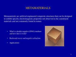
Definition Metamaterials are artificial structures that exhibit extreme values of effectiveεr i μr.
Metamaterials Do Not Exist • Artificial materials • Periodic structures • Period much smaller thenλ Homogenization of the structure Effective values of εrandμr
Left-Handed MM First Ideas Development Realization Applications
Other Quadrants? • Single-negative MM:εr<0 orμr<0 μr evanescent mode (plasma,metals@THz) propagation mode (isotropic dielectrics) εr evanescent mode (ferrites)
Veselago’s Intuition • Double-negative MM:εr<0 andμr<0 ? μr evanescent mode (plasma,metals@THz) propagation mode (isotropic dielectrics) εr ? evanescent mode (ferrites)
Conditions of Existence • No law of physics prevents the existence of DN MM • Generalized entropy conditions for dispersive media must be satisfied ()
Veselago’s Conclusions • Propagation constant βis real &negative Propagation mode exists Antiparalel group and phase velocities Backward propagation (Left-hand rule) Negative index of refraction
Synonyms • Double-Negative (DN) • Left-Handed (LH) • Negative Refraction Index (NRI) • (Metamaterials)
Left-Handed Metamaterials • Double-negative MM: εr<0 andμr<0 μr evanescent mode (plasma,metals@THz) propagation mode (isotropic dielectrics) εr propagation mode (Left-Handed MM) evanescent mode (ferrites)
Consequences of LH MM • Phenomena of classical physics are reversed : • Doppler effect • Vavilov-Čerenkov radiation • Snell’s law • Lensing effect • Goss-Henchen’seffect
Snell’s Law !!!
But Alas... Everything so far was “what if”... Can single- or double-negative materials really be made?
First SN MM – J. B. Pendry εr<0 - 1996. μr<0 - 1999.
Why is r negative? • Plasmons – phenomena ofexcitation in metals • Resonance of electron gas (plasma) • Plasmon produces a dielectric functionof the form: • Typically, fpis in the UV-range • Pendry: fp=8.2GHz
Experimental Validation • Smith, Shultz, et al. 2000.
LH MS Structures Resonant and non-resonant structures Applications
Resonant LH Structures • Split Ring Resonator (SRR) Very narrow LH-range Small attenuation • Many applications, papers, patents • Super-compact ultra-wideband (narrowband) band pass filters • Ferran Martin,Univ. Autonoma de Barcelona
Wide Stopband Garcia-Garcia et al,IEEE Trans. MTT, juni 2005.
Complementary SRR • Application of Babinet principle - 2004. • CSRR givesε‹0
LH BPF – CSRR/ Gap • November 2004. • Gaps contribute toμ‹0 • Low attenuation in the right stopband
BPF – CSRR/Stub • August 2005. • 90% BW • Not LH!!!
Three “Elements” • CSRR/Gap– steep left side • CSRR/Stub – steep right side • 2% BW
Multiple SRRsandSpirals Crnojević-Bengin et al, 2006.
Fractal SRRs Crnojević-Bengin et al, 2006.
Non-Resonant LH Structures • June 2002. • Eleftheriades • Caloz & Itoh • Oliner • Transmission Line (TL) approach • Novel characteristics: • Wide LH-range • Decreased losses
Conventional (RH) TL • Microstrip
LH TL • Dual structure
A Very Simple Proof • Analogy between solutions of the Maxwell’s equations for homogenous media and waves propagating on an LH TL Materials:LH TL: = !!!
Microstrip Implementation • Unit cell
Dispersion Diagrams RH TL LH TL
Is This Structure Purely LH? • Unit cell
CRLH TL • Real case – RH contribution always exists
LH TL Characteristics • Wide LH-range Caloz, Itoh, IEEE AP-S i USNC/URSI Meeting, juni 2002.
Applications of LH MM • Guided wave applications • Filters • Radiated wave applications • Antennas • Refracted wave applications • Lenses
Guided Wave Applications • Dual-bandand enhanced-bandwidth components • Couplers, phaseshifters, power dividers, mixers) • Arbitrary coupling-levelimpedance/phase couplers • Multilayer super-compactstructures • Zeroth-order resonatorswith constant field distribution Lai, Caloz, Itoh, IEEE Microwave Magazin, sept. 2004.
Dual-Band CRLH Devices • Second operating frequency: • Odd-harmonic - conventional dual-band devices • Arbitrary - dual-band systems • Phase-response curve of the CRLHTL : • DC offset – additionaldegree of freedom Arbitrary pair of frequenciesfor dual-band operation • Applications: Phaseshifters, matching networks, baluns, etc.
Dual-Band BLC Lin, Caloz, Itoh, IMS’03. • Conventional BLC operates atfand3f • RH TL replaced by CRLH TL arbitrary second passband
CµS/CRLH DCCaloz, Itoh, MWCL, 2004. • Conventional DC: broad bandwidth(>25%) loose coupling levels(<-10dB) • CRLH DC: 53% bandwidth coupling level −0.7dB
ZOR Sanada, Caloz, Itoh, APMC 2003. • Operates atβ=0 • Resonance independentof the length • Q-factor independent of the number of unit cells
SSSRCrnojević-Bengin, 2005. • LZOR=λ/5 • LSSSR=λ/16 • Easier fabrication • More robust to small changes of dimensions