Download

1 / 38
380 likes | 400 Vues
This article discusses the layout and features of micro-pattern gas detectors, specifically a gas-avalanche detector combining a gas layer as a signal generator with a CMOS readout pixel array. It also covers topics such as particle track identification and 3D track reconstruction.

E N D
Radius-wise track identification Vladimir Gromov Nikhef, Amsterdam, the Netherlands February 28, 2012
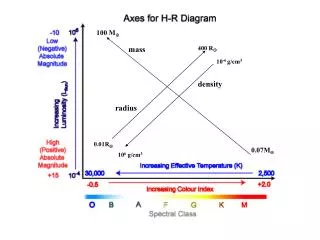
Micro-pattern gas detectors: layout and features Gas-avalanche detector combining a gas layer as signal generator with a CMOS readout pixel array Cathode (drift) plane Cluster1 Cluster2 1mm …1m → Drift gap Cluster3 Gas Amplification Structure 400V 50um → Avalanche gap Readout chip Cpar Front-end circuit • - particle track image (projection) • 3D track reconstruction • no sensor leakage current compensation • low parasitic capacitance (less than 10fF) • micro-discharges in avalanche gap • Gas volume = Correlated layers TWEPP-09 V.Gromov 22/09/09 2
Task definition: Lorenz force and particle trajectory F = q (V x B) • items to clarify: • mathematic formula describing trajectory of charged particle moving in magnetic field • definition of momentum of moving particle • check: … /Common doc/Conferences/TWEPP-10/physics for pedestrians.pdf and http://en.wikipedia.org/wiki/Momentum V B F Timepix-3 V.Gromov 13/03/12 3
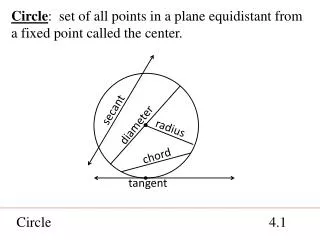
Detector layout Z coordinate = don’t care dimension Cilindric 3D coordinate system → Polar 2D coordinate system (transverse to Z-axis) 2D geometry : r = radius φ = azimuth angle Pixel array 2cm2 : 256 rows x 32 columns 480µ Common OR path ??? 55µ • items to clarify: • pT = transverse momentum or the momentum that is perpendicular to the beamline of a particle detector • why a high-pT particle moves radius-wise whereas a low-pT particle has a curved track Pixel array: 256rows x 32 cols z φ Periphery circuit E Contact pads high-pT B a few rows z 80cols●0.25mm = 20mm low-pT The first full scale prototype FE-I4A consists of an array of 80x336 pixels with a size of 50x250 µm2 organized in double-columns, and a periphery of height approx. 2 mm. Gas Volume drift gap @ 8mm 336rows●0.05mm = 16.8 mm many rows Pixel readout array Timepix-3 V.Gromov 13/03/12 4
Pixel matrix : charge collection related dead time Pixel array 2cm2 : 256 rows x 32 columns Occupancy: 0.25 ● 106 tracks ● cm-2 ● sec-1 6 ● 106 hits ● cm-2 ● sec-1 ( 8mm drift gap @ 3e-/mm) 12 MHz / chip 50kHz / column (every 20msec there is a hit pixel in the column) Assume 25ns is needed for column-wise readout (the whole column is dead) Chance to get a new hit during the dead time = 25ns / 20ms = 0.1% Charge collection-related dead time : Vdrift ● L gap = 25ns/mm ● 8mm = 200ns Common-column OR signal will be kept for 200ns (dead time) Data losses = 200ns / 20ms = 1 % 55µ z 220µ φ One-pixel- hit – the-whole-column-dead approach causes 1% data loses at the rate of 0.25 ● 106 tracks ● cm-2 ● sec-1 Timepix-3 V.Gromov 13/03/12 5
Pixel matrix : readout structure Col.1 Col.2 Col.3 Col.4 Correlated rows archtecture THR is not a level but transition 6 →7 Track ID ComOR 5 ComOR 4 W4 BXID_track BXID Pipeline & FIRI Track ID ComOR 3 ComOR 3 ComOR 4 ComOR 2 ComOR 1 Ncsim simulation with a realistic data = Matrix (rows state , BX) 128 x 128 Region Track Status Resolver ComOR 2 BXID_track W3 BXID Pipeline & FIRI Track ID ∑ > THR_track W2 BXID Pipeline & FIRI Definition of the row width, and dependence angle (pT) number of rows involved (pT) Global Track Status Resolver BXID_hit_4 BXID_hit_1 min BXID ≠ 0 z-1 z-1 z-1 BXID_track BXID min BXID ≠ 0 Columns are rows in fact BXID Pipeline Coordinate of the track = row with min BXID z-1 z-1 z-1 z-1 W1 ∑ ∑ ∑ ∑ Region Track Status Resolver Finite Impulse Response Integrator (FIRI) Timepix-3 V.Gromov 13/03/12 6
Pixel matrix : readout structure row.1 row.2 row.3 row.4 Coordinate of the track = row with min BXID THR is not a level but transition 6 →7 Track ID ComOR 5 ComOR 4 W4 BXID_track BXID Pipeline & FIRI Track ID ComOR 3 ComOR 3 ComOR 4 ComOR 2 ComOR 1 Region Track Status Resolver ComOR 2 Has been charged later on BXID_track W3 BXID Pipeline & FIRI Track ID ∑ THR_track 6 → 7 W2 BXID Pipeline & FIRI Global Track Status Resolver BXID_hit_4 BXID_hit_1 min BXID ≠ 0 z-1 z-1 z-1 BXID_track BXID min BXID ≠ 0 BXID Pipeline z-1 z-1 z-1 z-1 W1 ∑ ∑ ∑ ∑ Region Track Status Resolver Finite Impulse Response Integrator (FIRI) Timepix-3 V.Gromov 13/03/12 7
Pixel array 2cm2 : 256 rows x 32 columns z z 3 3 E a few pixel high-pT B low-pT 2 2 many pixels Gas Volume drift gap @ 8mm 1 1 Columns are rows in fact Pixel readout array φ φ Leftward Shift register Rightward Shift register Coordinate of the track = row with min BXID THR is not a level but transition 6 →7
Col. 4 E Col. 3 Col. 2 Col. 1 low-pT B 8mm Columns are rows in fact Coordinate of the track = row with min BXID THR is not a level but transition 6 →7 Timepix-3 V.Gromov 13/03/12 9
High-pT track response Col. 4 E Col. 3 Col. 2 high-pT B Col. 1 = coordinate 8mm θ= arctg [1●55µm/ 8mm ] THR_track BX k-1 k k+1 k+2 k+3 k+4 k+5 k+6 k+7 k+8 k+9 k+10 k+11 k+12 k+13 k+14 k+15 k+16 Col. 1 THR_track BX_hit.1 W1 THR_hit Col. 2 Columns are rows in fact Col. 3 Coordinate of the track = row with min BXID THR is not a level but transition 6 →7 Col. 4 Timepix-3 V.Gromov 13/03/12 10
High-pT track response row47 low-pT B row37 θ high-pT BX k-1 k k+1 k+2 k+3 k+4 k+5 k+6 k+7 k+8 k+9 k+10 k+11 k+12 k+13 k+14 k+15 k+16 drift gap (10mm) 8row OR row14 THR_track BX_hit.1 FIRI out Timepix-3 V.Gromov 13/03/12 11
Low- pT track response Col. 4 E Col. 3 Col. 2 low-pT B Col. 1 = coordinate θ 8mm BX k-1 k k+1 k+2 k+3 k+4 k+5 k+6 k+7 k+8 k+9 k+10 k+11 k+12 k+13 k+14 k+15 k+16 k+17 Col. 1 W1 THR_hit BX_hit.1 Col. 2 THR_hit W2 BX_hit.2 Col. 3 W3 THR_hit BX_hit.3 Col. 4 W4 THR_hit BX_hit.4 Timepix-3 V.Gromov 13/03/12 12
Low- pT track response Col. 4 E Col. 3 Col. 2 low-pT B Col. 1 = coordinate θ 8mm θ= arctg [4●55µm/ 8mm ] THR_track BX k-1 k k+1 k+2 k+3 k+4 k+5 k+6 k+7 k+8 k+9 k+10 k+11 k+12 k+13 k+14 k+15 k+16 k+17 Col. 1 W1 THR_hit BX_hit.1 Col. 2 THR_hit W2 BX_hit.2 Columns are rows in fact Col. 3 W3 THR_hit Coordinate of the track = row with min BXID BX_hit.3 Col. 4 W4 THR_hit BX_hit.4 Timepix-3 V.Gromov 13/03/12 13
Destrete-time digital fimit impule response filter A discrete-time FIR filter of order N. The top part is an N-stage delay line with N + 1 taps. Each unit delay is a z−1 operator in Z-transform notation. OR
Types of Digital Filters The input xn and output yn sequences of a digital filter both represent signals sampled at discrete, uniformly spaced, time increments tn. A finite impulse response (FIR) digital filter takes N+1 of the most recent input samples of xn, multiplies them by N+1 coefficients, and sums the result to form yn. For an infinite impulse response (IIR) filter, the M previous output samples of yn are weighted and added in as well. In other words, an IIR filter uses feedback. This is expressed mathematically by All of the a's are zero for a FIR filter. The main advantage of IIR filters is that they can produce a steeper slope for a given number of coefficients. The main advantage of FIR filters is that the group delay is constant. This provides the capability of obtaining both a steep cutoff and perfect phase response. This is impossible to achieve with an analog filter. Filter Transfer Functions and the z-transform The frequency domain response, or transfer function can be obtained from a z-transform, which is defined by With r=1, equation (2) is the discrete Fourier transform of y, so evaluating Y with r=1 yields the frequency response. Using the fact that The z-transform of equation (1) is Then the transfer function is given by
$display - Print to screen a line followed by an automatic newline. $write - Write to screen a line without the newline. $swrite - Print to variable a line without the newline. $sscanf - Read from variable a format-specified string. (*Verilog-2001) $fopen - Open a handle to a file (read or write) $fdisplay - Write to file a line followed by an automatic newline. $fwrite - Write to file a line without the newline. $fscanf - Read from file a format-specified string. (*Verilog-2001) $fclose - Close and release an open file handle. $readmemh - Read hex file content into a memory array. $readmemb - Read binary file content into a memory array. $monitor - Print out all the listed variables when any change value. $time - Value of current simulation time. $dumpfile - Declare the VCD (Value Change Dump) format output file name. $dumpvars - Turn on and dump the variables. $dumpports - Turn on and dump the variables in Extended-VCD format. $random - Return a random value. The $readmemb system task in Verilog allows a program to read data from a text file with binary formatted data. For example, if a file test_data_bin.dat contains the data 00000001000000010000000100000001 11111111111111111111111111111111 01010101010101010101010101010101 00000000000000000000000000000000 10101010101010101010101010101010 01010111110101111110101111101111 11111111111111111111111111111111 10101010101010101010101010101010 Then this snippet can read in this data and display itmoduleverilog_readmemb; reg[31:0]data_ram[0:7]; integer ii; initialbegin $readmemb("test_data_bin.dat",data_ram); for(ii=0;ii<8;ii=ii+1)$display("%x",data_ram[ii]); $stop; end endmodule • ...) ; $fstrobe (arguments) ; $fmonitor (arguments) ; $readmemb ("file", memory_identifier [,begin_address[ ... • data from a file and store it in memory, use the functions: $readmemb and $readmemh . • The $readmemb task reads binary data and $readmemh reads hexadecimal data. Data has to exist ... [3:0] • memory [15:0] ; initial begin $readmemb ("data.bin", memory) ; end Loading data in...http://www.verilog.renerta.com/source/vrg00016.htm • 2. Verilog - PLA Modeling Tasks - verilog.renerta.com • ... tasks are used to model content addressed memories i.e., memories that are read at locations that an • input address matches a stored address. The PLA devices can be synchronous or asynchronous • (type is defined by array_type : sync and async ). All patterns should be loaded into memory using • the $readmemb and $readmemh system tasks or assigned by procedural assignments. • Both the input_terms and the output_terms should be concatenations of scalar variables, • but all variables from the output_terms should be declared as a reg data type. • The input_terms should have the length equal to the memory word size...http://www.verilog.renerta.com/source/vrg00034.htm
Task definition - High pT threshold ( 3Gev/c) → θ = 5.7° 8 rows in the group 8● 0.11mm / 10mm = arc tangens (5.7°) - Drift Gap = 10mm →Drift time = 200ns = 8BX row47 low-pT B row37 θ high-pT drift gap (10mm) row14 Timepix-3 V.Gromov 13/03/12 17
Pixel matrix : readout structure Pixel Array Periphery Common-row-OR DTF COMP FIFO Redundancy Correction VETO Redundancy Correction DTF COMP FIFO VETO Redundancy Correction DTF COMP FIFO VETO Redundancy Correction DTF COMP FIFO VETO Redundancy Correction DTF COMP Periphery Bus FIFO VETO 128 rows (pixel :110µm x 220µm) Redundancy Correction FIFO DTF COMP VETO Redundancy Correction FIFO DTF COMP VETO Digital Time Filter (DTF) FIFO COMP THR from 7 rows UP High_pT BX_ID & ROW_ID VETO from 7 rows DOWN IN z-1 z-1 z-1 z-1 OUT ∑ ∑ ∑ ∑ 8 BX Frame Integrator End-of-Chip FIFO IN z-1 z-1 z-1 z-1 z-1 z-1 z-1 OUT 8-Row Group Pipeline (4BX deep) BXID min BXID ≠ 0 BXID Pipeline (9BX deep) Timepix-3 V.Gromov 21/03/12 18
Format of the input data Common OR / ROW / BX RowID = 0 RowID = 127 BXID = 0 0000000000000000000000000000000000000000000000000000000000000 0000000000000000000000000000000000000000000000000000000000000 0010000000000000000001000000000000000000001000000000000000000 0001000000000000000001000000000000000000010000000000000000000 0000100000000000000001000000000000000000100000000000000000000 0000010000000000000001000000000000000001000000000000000000000 0000001000000000000001000000000000000010000000000000000000000 0000000100000000000001000000000000000100000000000000000000000 0000000010000000000001000000000000001000000000000000000000000 0000000001000000000001000000000000010000000000000000000000000 0000000000000000000000000000000000000000000000000000000000000 0000000000000000000000000000000000000000000000000000000000000 0000000000000000000000000000000000000000000000000000000000000 8 BX = 200ns Track Appearance Time BXID = 12 LOW pT (pos. charged) LOW pT (neg. charged) HIGH pT High pT Trigger V.Gromov 15/03/12 19
Proposed readout structure : RTL simulation 00000000000000000000000000000000000000000000000000000000000000000000000000000000000000000000000000000000000000000000000000000000 00000000000000000000000000000000000000000000000000000000000000000000000000000000000000000000000000000000000000000000000000000000 00000000100000000000000000000000000000000000000000000000000000000000000000000000000000000000000000000000000000000000000000000000 00000000100000000000000000000000000000000000000000000000000000000000000000000000000000000000000000000000000000000000000000000000 00000000100000000000000000000000000000000000000000000000000000000000000000000000000000000000000000000000000000000000000000000000 00000000100000000000000000000000000000000000000000000000000000000000000000000000000000000000000000000000000000000000000000000000 00000000100000000000000000000000000000000000000000000000000000000000000000000000000000000000000000000000000000000000000000000000 00000000100000000000000000000000000000000000000000000000000000000000000000000000000000000000000000000000000000000000000000000000 00000000100000000000000000000000000000000000000000000000000000000000000000000000000000000000000000000000000000000000000000000000 00000000100000000000000000000000000000000000000000000000000000000000000000000000000000000000000000000000000000000000000000000000 00000000000000000000000000000000000000000000000000000000000000000000000000000000000000000000000000000000000000000000000000000000 00000000000000000000000000000000000000000000000000000000000000000000000000000000000000000000000000000000000000000000000000000000 00000000000000000000000000000000000000000000000000000000000000000000000000000000000000000000000000000000000000000000000000000000 00000000000000000000000000000000000000000000000000000000000000000000000000000000000000000000000000000000000000000000000000000000 00000000000000000000000000000000000000000000000000000000000000000000000000000000000000000000000000000000000000000000000000000000 00000000000000000000000000000000000000000000000000000000000000000000000000000000000000000000000000000000000000000000000000000000 00000000000000000000000000000000000000000000000000000000000000000000000000000000000000000000000000000000000000000000000000000000 00000000000000000000000000000000000000000000000000000000000000000000000000000000000000000000000000000000000000000000000000000000 00000000000000000000000000000000000000000000000000000000000000000000000000000000000000000000000000000000000000000000000000000000 00000000000000000000000000000000000000000000000000000000000000000000000000000000000000000000000000000000000000000000000000000000 00000000000000000000000000000000000000000000000000000000000000000000000000000000000000000000000000000000000000000000000000000000 00000000000000000000000000000000000000000000000000000000000000000000000000000000000000000000000000000000000000000000000000000000 00000000000000000000000000000000000000000000000000000000000000000000000000000000000000000000000000000000000000000000000000000000 00000000000000000000000000000000000000000000000000000000000000000000000000000000000000000000000000000000000000000000000000000000 00000000000000000000000000000000000000000000000000000000000000000000000000000000000000000000000000000000000000000000000000000000 00000000000000000000000000000000000000000000000000000000000000000000000000000000000000000000000000000000000000000000000000000000 00000000000000000000000000000000000000000000000000000000000000000000000000000000000000000000000000000000000000000000000000000000 00000000000000000000000000000000000000000000000000000000000000000000000000000000000000000000000000000000000000000000000000000000 00000000000000000000000000000000000000000000000000000000000000000000000000000000000000000000000000000000000000000000000000000000 00000000000000000000000000000000000000000000000000000000000000000000000000000000000000000000000000000000000000000000000000000000 00000000000000000000000000000000000000000000000000000000000000000000000000000000000000000000000000000000000000000000000000000000 00000000000000000000000000000000000000000000000000000000000000000000000000000000000000000000000000000000000000000000000000000000 00000000000000000000000000000000000000000000000000000000000000000000000000000000000000000000000000000000000000000000000000000000 00000000000000000000000000000000000000000000000000000000000000000000000000000000000000000000000000000000000000000000000000000000 00000000100000000000000000000000000000000000000000000000000000000000000000000000000000000000000000000000000000000000000000000000 00000000010000000000000000000000000000000000000000000000000000000000000000000000000000000000000000000000000000000000000000000000 00000000001000000000000000000000000000000000000000000000000000000000000000000000000000000000000000000000000000000000000000000000 00000000000100000000000000000000000000000000000000000000000000000000000000000000000000000000000000000000000000000000000000000000 00000000000010000000000000000000000000000000000000000000000000000000000000000000000000000000000000000000000000000000000000000000 00000000000001000000000000000000000000000000000000000000000000000000000000000000000000000000000000000000000000000000000000000000 00000000000000100000000000000000000000000000000000000000000000000000000000000000000000000000000000000000000000000000000000000000 00000000000000010000000000000000000000000000000000000000000000000000000000000000000000000000000000000000000000000000000000000000 00000000000000000000000000000000000000000000000000000000000000000000000000000000000000000000000000000000000000000000000000000000 00000000000000000000000000000000000000000000000000000000000000000000000000000000000000000000000000000000000000000000000000000000 00000000000000000000000000000000000000000000000000000000000000000000000000000000000000000000000000000000000000000000000000000000 00000000000000000000000000000000000000000000000000000000000000000000000000000000000000000000000000000000000000000000000000000000 RowID = 8 BXID_hit = 3 high pT track RowID = 8 BXID_hit = 3510= 2316 high pT track Timepix-3 V.Gromov 21/03/12 20
High-pT track response row47 low-pT B row37 θ high-pT BX k-1 k k+1 k+2 k+3 k+4 k+5 k+6 k+7 k+8 k+9 k+10 k+11 k+12 k+13 k+14 k+15 k+16 drift gap (10mm) 8row OR row14 THR_track BX_hit.1 Integrator Timepix-3 V.Gromov 13/03/12 24
row #0 row #60 High pT tracks BC #0 0000000000000000000000000000000000000000000000000000000000000 0000000000000000000000000000000000000000000000000000000000000 0000000000000000000001000000000000000000000001000000000000000 0000000000000000000001000000000000000000000000100000000000000 0000000000000000000001000000000000000000000000010000000000000 0000000000000000000001000000000000000000000000001000000000000 0000000000000000000001000000000000000000000000000100000000000 0000000000000000000001000000000000000000000000000010000000000 0000000000000000000001000000000000000000000000000001000000000 0000000000000000000001000000000000000000000000000000100000000 0000000000000000000000000000000000000000000000000000000000000 0000000000000000000000000000000000000000000000000000000000000 0000000000000000000000000000000000000000000000000000000000000 Original data BX#12 BC #0 0000000000000000000000000000000000000000000000000000000000000 0000000000000000000000000000000000000000000000000000000000000 000000000000001111111100000000000000001111111100000000000000 000000000000001111111100000000000000000111111110000000000000 000000000000001111111100000000000000000011111111000000000000 000000000000001111111100000000000000000001111111100000000000 000000000000001111111100000000000000000000111111110000000000 000000000000001111111100000000000000000000011111111000000000 000000000000001111111100000000000000000000001111111100000000 000000000000001111111100000000000000000000000111111110000000 0000000000000000000000000000000000000000000000000000000000000 0000000000000000000000000000000000000000000000000000000000000 0000000000000000000000000000000000000000000000000000000000000 Dynamic Frames (8 OR) BX#12 0000000000000000000000000000000000000000000000000000000000000 0000000000000000000000000000000000000000000000000000000000000 000000000000001111111100000000000000001111111100000000000000 000000000000002222222200000000000000001222222210000000000000 000000000000003333333300000000000000001233333321000000000000 000000000000004444444400000000000000001234444432100000000000 000000000000005555555500000000000000001234555543210000000000 000000000000006666666600000000000000001234566654321000000000 000000000000007777777700000000000000001234567765432100000000 000000000000008888888800000000000000001234567876543210000000 000000000000007777777700000000000000000123456776543210000000 000000000000006666666600000000000000000012345666543210000000 000000000000005555555500000000000000000001234555543210000000 BC #0 Integration in time (8 BX) BX#12 0000000000000000000000000000000000000000000000000000000000000 0000000000000000000000000000000000000000000000000000000000000 0000000000000000000000000000000000000000000000000000000000000 0000000000000000000000000000000000000000000000000000000000000 0000000000000000000000000000000000000000000000000000000000000 0000000000000000000000000000000000000000000000000000000000000 0000000000000000000000000000000000000000000000000000000000000 000000000000001111111100000000000000000000001100000000000000 000000000000001111111100000000000000000000001110000000000000 000000000000001111111100000000000000000000000110000000000000 0000000000000000000000000000000000000000000000000000000000000 0000000000000000000000000000000000000000000000000000000000000 0000000000000000000000000000000000000000000000000000000000000 BC #0 Comparator output (THR=7) BX#12
Low pT tracks row #0 row #60 0000000000000000000000000000000000000000000000000000000000000 0000000000000000000000000000000000000000000000000000000000000 000000000000000000000011111111111111110000000000000000000000 000000000000000000000011111111111111110000000000000000000000 0000000000000000000000000000000000000000000000000000000000000 0000000000000000000000000000000000000000000000000000000000000 0000000000000000000000000000000000000000000000000000000000000 0000000000000000000000000000000000000000000000000000000000000 0000000000000000000000000000000000000000000000000000000000000 0000000000000000000000000000000000000000000000000000000000000 0000000000000000000000000000000000000000000000000000000000000 0000000000000000000000000000000000000000000000000000000000000 0000000000000000000000000000000000000000000000000000000000000 BC #0 Original data BX#12 0000000000000000000000000000000000000000000000000000000000000 0000000000000000000000000000000000000000000000000000000000000 0000000000000001111111111111111111111111111110000 0000000000 000000000000000111111111111111111111111111111000000000000 00 0000000000000000000000000000000000000000000000000000000000000 0000000000000000000000000000000000000000000000000000000000000 0000000000000000000000000000000000000000000000000000000000000 0000000000000000000000000000000000000000000000000000000000000 0000000000000000000000000000000000000000000000000000000000000 0000000000000000000000000000000000000000000000000000000000000 0000000000000000000000000000000000000000000000000000000000000 0000000000000000000000000000000000000000000000000000000000000 0000000000000000000000000000000000000000000000000000000000000 BC #0 Dynamic Frames (8 OR) BX#12 0000000000000000000000000000000000000000000000000000000000000 0000000000000000000000000000000000000000000000000000000000000 0000000000000001111111111111111111111111111110000 0000000000 000000000000000222222222222222222222222222222000000000000 00 000000000000000222222222222222222222222222222 00000000000000 000000000000000222222222222222222222222222222 00000000000000 000000000000000222222222222222222222222222222 00000000000000 00000000000000022222222222222222222222222222200000000000000 000000000000000222222222222222222222222222222 00000000000000 00000000000000022222222222222222222222222222200000000000000 00000000000000011111111111111111111111111111100000000000000 0000000000000000000000000000000000000000000000000000000000000 0000000000000000000000000000000000000000000000000000000000000 BC #0 Integration in time (8 BX) BX#12
Row dynamic frame definition High pT threshold ( 3Gev/s) → θ = 5.7° 8 rows in the group 8● 0.11mm / 10mm = arc tangens (5.7°) row47 low-pT B row37 θ high-pT drift gap (10mm) row14 Timepix-3 V.Gromov 13/03/12 27
Col. 4 E Col. 3 Col. 2 8mm B Col. 1 = coordinate high-pT z-1 z-1 z-1 OUT IN Pipeline (4BX deep) + OR
Uses all 8 metal layers Encounter 09.12-s159_1 (64bit) (Linux 2.6) Power Domain used: VDD Voltage: 1.4 * Primary Input Activity: 0.200000 * Power Units = 1mW * Clock: clk_40 Clock Period: 0.020500 usec ----------------------------------------------------------------------------------------- Switching Leakage Total Power Power Power ----------------------------------------------------------------------------------------- 2.811mW 2.507mW 5.318mW 16 row layout and power
Some ideas of the Gas pixel L1 trigger organization:Status registers Shows bit in the 250 ns before BX Each pixel has 8 (4) bit status registers covering 250 ns. Each BX all registers shift by 25 (50) ns 250 ns is a drift time OR OR S > Amp. Analog sum over all the pixels in the column OR Local Pixel RoI Shows bit in the present BX
Common-per-column OR cell OR charging RC - transmission line 55μm x 8 = 440μm C load= 118fF from pixel N-1 OR EoC logic OR OR 56ps Cin_OR = 17.6fF real OR & real RC-line 32ps Pixel N Pixel N+1 Pixel N+2 real OR & ideal RC-line 16ps Ideal OR & real RC-line 1 Column = 32 pixels = 440μm x 32 = 1.408cm delay = 60 ps / pixel Timepix-2 V.Gromov 23/11/10 33
Through-column Propagation of the Common OR signal Typical case: process corner=tt , vdd=1.5V, temp=27°C posedge skew ≈ 2ns Timepix-2 V.Gromov 23/11/10 34
Through-column Propagation of the Common OR signal Slow case = worst case: process corner=ssf , vdd=1.2V, temp=70°C posedge skew ≈ 4ns negedge skew ≈ 8ns Timepix-2 V.Gromov 23/11/10 35
Through-column Propagation of the Common OR signal Typical case: process corner=tt , temp=27°C Power supply voltage effects posedge skew ≈ 2.6 ns Timepix-2 V.Gromov 23/11/10 36
Through-column Propagation of the Common OR signal Typical case: process corner=tt , vdd=1.5V Temperature effects posedge skew ≈ 2.2 ns Timepix-2 V.Gromov 23/11/10 37
Through-column Propagation of the Common OR signal Typical case: process corner=tt , vdd=1.5V, temp=27C Power consumption 12●10-12A ● sec● hit -1 ● 50 000 hit ● sec-1 ●column-1 ●1.5V= 1 µW ●column-1 Power = 256 µW / chip Timepix-2 V.Gromov 23/11/10 38