Download
1 / 4
40 likes | 175 Vues
This document details the design of a voltage-controlled pulse driver operating between 3.3V and 5V, suitable for generating controlled pulses varying from 0 to 8V with a capacitance of 100fF. It emphasizes the importance of using optimal component sizes and types, such as small ceramic chip components and AVX thin-film capacitors, for enhanced performance. The circuit aims for fast signal transitions, with recommendations for bypass capacitors and substrate grounding. The potential for dual or triple pulse output is also discussed, inviting feedback on pulse separation preferences.

E N D
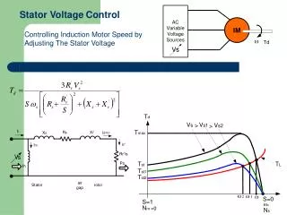
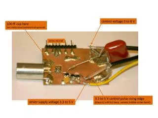
control voltage 0 to 8 V 100 fF cap here (on a little island isolated from ground) ignore, old stuff 3.3 to 5 V control pulse rising edge (there is a 49.9 Ω term. resistor hidden under here!) driver supply voltage 3.3 to 5 V
do not exceed 10 V !! could be bigger some bypass caps could be smaller low leakage is best 3.3 to 5 V in out best use SMA BSS83 tie substrate to ground! For simplicity, I did not use C2 and had C1+C1 = 0.1pF (i.e. if I had used two caps in series they would be 0.2pF). But, I suggest do use the T circuit, use C1=0.5pF and figure C2 for the amplitude you like at a good convenient voltage I suggest VC=3.0V is nice for the nominal amplitude out.
Detailed parts choices depends on your prototyping skills, experience, and available tools, and of course on availability. The circuit shown in the picture was not originally intended to be as fast as possible. The parts and construction techniques are sub-optimal. Use the smallest parts you can handle, on the signal path. Optimal performance will come from 0402 resistors and capacitors and very short connections. Of course, small ceramic chip resistors and capacitors are small, and fragile, so it may be a pain to prototype with. I suggest AVX thin film capacitors for <10pF values (you can buy from Digi-Key), any C0G capacitor for other signal path elements (such as C2 on previous page). Better performance will come from an SMA connector on the output, depending of course on how you connect to it and what you plug in there...
For the “real” printed circuit board version of this thing, I will include double-pulse capability (maybe triple?) by replicating the pulser transistor and capacitors, and probably modifying the driver circuitry. Gary – please comment on what range of double-pulse separation is most interesting to test with. Should it go down to zero, or is it ok if there is a minimum ~5ns pulse separation? The issue is, do we have one control input (pulse it twice), or two? Reminder for the record of the output you should see from prototype described above