Class 2 Continuous Load Path Concepts
Class 2 Continuous Load Path Concepts. Load Paths. Loads must go to “ground” Vertical loads Gravity Uplift Lateral loads Wind Earthquake Flood. Load Paths. Bridge loads Headers Beams Girders Interaction with the ground Shallow – spread, slab, stem wall

Class 2 Continuous Load Path Concepts
E N D
Presentation Transcript
Load Paths • Loads must go to “ground” • Vertical loads • Gravity • Uplift • Lateral loads • Wind • Earthquake • Flood Building Design – Fall 2007
Load Paths • Bridge loads • Headers • Beams • Girders • Interaction with the ground • Shallow – spread, slab, stem wall • Deep – piles, caissons, friction, bearing • Possible failures – slope failure, liquefaction, erosion, excessive moisture Building Design – Fall 2007
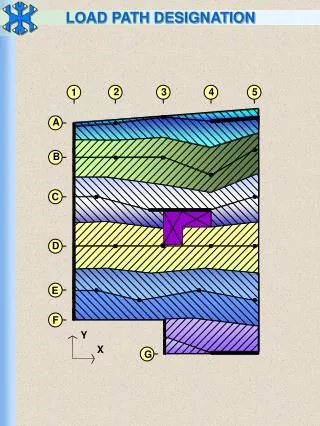
Load PathsVertical Building Design – Fall 2007
Deck collapse – gravity failure Building Design – Fall 2007
Foundation gravity failure Building Design – Fall 2007
Uplift failure Building Design – Fall 2007
Uplift column failure Building Design – Fall 2007
Flood Building Design – Fall 2007
Lateral displacement Building Design – Fall 2007
Earthquake Building Design – Fall 2007
Wind Building Design – Fall 2007
Vertical and Lateral paths OK Building Design – Fall 2007
Lateral failure from wind Building Design – Fall 2007
Lateral wind failure Building Design – Fall 2007
Slope failure Building Design – Fall 2007
Masonry piers Building Design – Fall 2007
Beams – carrying loads Building Design – Fall 2007
Headers: bridging loads Building Design – Fall 2007
WTC-7 (Bridging loads failure) • 47 story building • housed city’s OEM • some missile impacts • burned uncontrolled for 8 hours • 7 story electric substation • diesel fuel in building in several tanks Building Design – Fall 2007
WTC 7 - 7th Floor Plan Building Design – Fall 2007
WTC 7 Penthouses start to collapse Building Design – Fall 2007
WTC 7 Interior collapse continues - note the “kink” Building Design – Fall 2007
Load Path Concepts • Materials chosen with sufficient strength • Connections made with sufficient size, strength, and number • Any weak link could be a failure point • Load path requires appropriate soil bearing capacity • Soil must be able to maintain bearing capacity Building Design – Fall 2007
Vertical gravity loads • Creates compression in members • Creates shear in connections • What materials and connections perform well in compression? Building Design – Fall 2007
Vertical gravity loads • Masonry • Concrete • Steel • Wood (of proper size) • Reinforcing steel for masonry and concrete • Bolts Building Design – Fall 2007
Vertical gravity load • Compression failures are most likely…? • Buckling Building Design – Fall 2007
Vertical uplift loads • Creates tension in members • Creates shear or withdrawal in connections • What materials and connections perform well in tension? Building Design – Fall 2007
Vertical uplift loads • Steel • Wood • Bolts or welding for steel • Bolts for wood Building Design – Fall 2007
Lateral loads • Creates compression in wall panels • Creates bending in single members • Creates shear at panel edges • Creates compression in struts between panels or members Building Design – Fall 2007
Homework 1 – Due 9/12/07 • Find and mark the load paths on the 2 attached sketches • Sketch headers, girders or beams as bridging loads • Take the loads into the foundation which is a pile system Name: ____________________________ Building Design – Fall 2007
Pilelayout Building Design – Fall 2007
References • Masonry Structures – text by Drysdale • Design of Wood Structures – text by Breyer • ASCE 7 • ACI 530 • NDS • Class web page Building Design – Fall 2007