Download
1 / 7
70 likes | 187 Vues
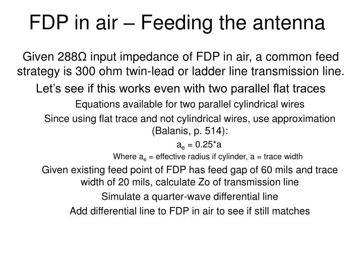
FDP in air – Feeding the antenna. Given 288 Ω input impedance of FDP in air, a common feed strategy is 300 ohm twin-lead or ladder line transmission line. Let’s see if this works even with two parallel flat traces Equations available for two parallel cylindrical wires

E N D
FDP in air – Feeding the antenna • Given 288Ω input impedance of FDP in air, a common feed strategy is 300 ohm twin-lead or ladder line transmission line. • Let’s see if this works even with two parallel flat traces • Equations available for two parallel cylindrical wires • Since using flat trace and not cylindrical wires, use approximation (Balanis, p. 514): • ae = 0.25*a • Where ae = effective radius if cylinder, a = trace width • Given existing feed point of FDP has feed gap of 60 mils and trace width of 20 mils, calculate Zo of transmission line • Simulate a quarter-wave differential line • Add differential line to FDP in air to see if still matches
FDP in air – Feeding the antenna (cont) To test if 333Ω is correct, let’s feed the antenna with a quarter wave (90°) line. Given a load of 288Ω, the impedance should be 385Ω at the end of the quarter wave transformer.
FDP in air – Feeding the antenna (cont.) 288Ω • Simulate just the differential line to verify the Zo calculation and expected impedance at end of quarter-wave differential line • It works! 1205 mils 90° Momentum 50Ω
FDP in air – Feeding the antenna (cont.) • Now with the antenna and the same quarter-wave differential line • Not 385Ω at input anymore? Capacitance between lines and antenna? 1205 mils 90° 50Ω Momentum
Test board 1 L On both boards, the FDP, feedlines, and layer stacking (~62 mil board) are identical. Test board 1 is for the balun measurement and board 2 is for the two-port measurement. L = 1757 mils w = 83 mils g = 59 mils d = 237.5 mils trace width = 20 mils w d g 50Ω line Test board 2 50Ω lines
Test boards 1 & 2: Balun and Two-port Measurements and Simulations Simulations Measurements Two internal ports One internal port Two-port Balun BW = 45MHz 62MHz 70MHz 63MHz 80-j*74Ω source