Download
1 / 28
290 likes | 513 Vues
Explore the nature of polarized light, its phases, and how to observe and control polarization. Dive into linear, circular, and elliptical polarization, including the trajectories of the E-vector, tilting angles, and sense of rotation. Learn about the synthesis of circularly and linearly polarized waves and the generation of elliptical light. Discover the relationship between Ex and Ey in different polarization states and how angular momentum is related to circularly polarized light. Delve into the mechanisms of polarizers, Malus's law, dichroism, birefringence, and the properties of optic axes in birefringent crystals like Calcite.

E N D
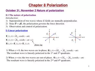
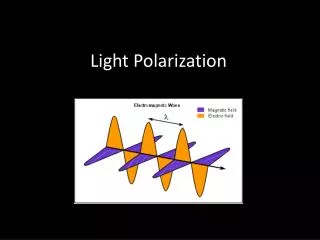
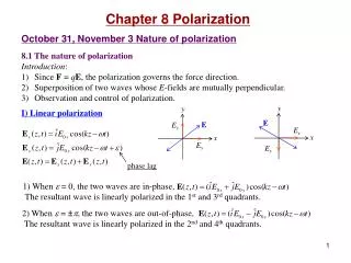
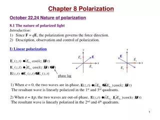
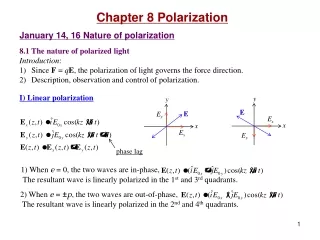
y y E E Ey Ex x x Ex Ey Chapter 8 Polarization January 14, 16 Nature of polarization 8.1 The nature of polarized light Introduction: • SinceF= qE, the polarization of light governs the force direction. • Description, observation and control of polarization. I) Linear polarization phase lag 1) When e = 0, the two waves are in-phase, The resultant wave is linearly polarized in the 1st and 3rd quadrants. 2) When e = ±p, the two waves are out-of-phase, The resultant wave is linearly polarized in the 2nd and 4th quadrants.
y E0 E0 E E0 E0 wt x x -wt E y II) Circular polarization 1) When E0x=E0y=E0, e = -p /2 , a = kz-wt, the resultant wave is right-circularly polarized (rotating clockwise). 2) When E0x=E0y=E0, e = p /2 , a = -kz +wt, the resultant wave is left-circularly polarized (rotating counterclockwise). Circular light: The amplitude E0 does not change. The direction of E rotates. The end point of E traces out a circle. A circularly polarized wave can be synthesized by two orthogonally linearly polarized waves of equal amplitude. A linearly polarized wave can be synthesized by two oppositely polarized circular waves of equal amplitude.
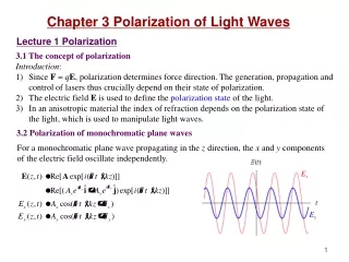
E0y E a E0x III) Elliptical polarization Elliptical light: The E vector rotates and changes its magnitude as well. The end point of E traces out an ellipse. For a harmonic wave propagating in the z direction, its two components on the x and y axes are 1) Trajectory of the E vector. Let us eliminate kz-wt and see what the relation between Ex and Ey is: In the Ex-Ey plane this is an ellipse.
E0y E a E0x 2) Tilting angle of the ellipse. The tilting angle a is given by When e = ±p /2, we have When e = 0, ±p, we have 3) Sense of rotation of the ellipse.
e = 0 p/4 p/2 3p/4 p 5p/4 3p/2 7p/4 2p Example: State of polarization: Right-circular light: R-state Left-circular light: L-state Linearly polarized light: P-state, superposition of R- and L-states with equal amplitude. Elliptically polarized light: E-state, superposition of R- and L-states with different amplitudes.
Nature light: Each atom emits a polarized wave train of ~ 10-8s. The wave trains are random in polarization. As a result, nature light is unpolarized, or randomly polarized. 8.1.5 Angular momentum and the photon picture Circularly polarized light sets a charge into circular motion. E-field exerts a torque on the charge: (with the same frequency as light) Newton’s second law for rotation: (L is the angular momentum of the charge) Power generated by a torque: Direction of L: -k for R-state, +k for L-state (right-hand rule). When a circularly polarized photon is absorbed, it transfers an angular momentum: The intrinsic angular momentum (spin) of a photon is .
Reading: How is oriented in space? Answer: In polar coordinates, Suppose one of the two axes of the ellipse are oriented at angle qm, then
Read: Ch8: 1 Homework: Ch8: 6,8,9 Due: January 25
January 18, 23 Birefringence 8.2 Polarizers Polarizer:An optical device whose output is a certain form of polarized light. Example: Linear polarizers, circular polarizers. Polarizer and analyzer, transmission axis, extinction axis Physical mechanisms of polarizers: • Dichroism (selective absorption) • Reflection • Scattering • Birefringence (double refraction) Malus’s law: Transmitted intensity E01 E02 q Example 8.3
8.3 Dichroism Dichroism:Selective absorption of one of the two orthogonal P-state light. Wire-grid polarizers: The transmission axis of the grid is perpendicular to the wires. Dichroic crystals: (example: tourmaline) The E-field perpendicular to the optic axis is strongly absorbed. Polaroids: Dichroic sheet polarizers.
Absorption band, polarizers ny nx Birefringence Optic axis e-ray o-ray 8.4 Birefringence Anisotropy of the binding force of an electron cloud causes the anisotropy in the refractive indexes for different light polarizations. 8.4.1 Calcite (CaCO3) Optic axis: Inside the (uniaxial) crystal there is a special direction along which when light is propagating there is no birefringence occurs. This direction is called the optic axis. Principal plane: A plane that contains the optic axis and the ray direction. Ray direction: Energy flow direction. The refractive index depends on whether the E-field is parallel or perpendicular to the principal plane. o-ray: E-field normal to the principal plane. e-ray: E-field parallel to the principal plane. Ee Eo
o-ray Optic axis e-ray Optic axis Principle:Light whose polarization is parallel to the optic axis feels a refractive index of ne and propagates with a speed of v//. Light whose polarization is perpendicular to the optic axis feels a refractive index of no and propagates with a speed of v┴. Huygens’s explanation: o-ray, wavelets expand with v┴. e-ray, E-field component parallel to the optic axis propagates with v//. E-field component perpendicular to the optic axis propagates with v┴. This results in elliptical wavelets with a spheroid shape whose axis is the optic axis of the crystal. Wave front : the envelope of the wavelets. Ray direction: from the origin of each wavelet to its tangent point on the wave front. In a birefringent material the ray direction is generally different from the wave vector direction. 8.4.2 Birefringent crystals Cubic, uniaxial, biaxial crystals. Negative (ne<no)and positive (ne>no) uniaxial birefringent crystals.
v// v┴ Optic axis o-wave e-wave Mostly o-ray 38.5º v// e-ray v┴ Optic axis e-wave o-wave Ordinary and extraordinary wavelets in uniaxial crystals: Glan-Foucault polarizer Positive uniaxial crystal Negative uniaxial crystal 8.4.3 Birefringent polarizers Example: Glan-Foucault (Glan-Air) polarizer. Calcite, no=1.6584, ne=1.4864 qc(o-ray) =37.08º, qc(e-ray) =42.28º. qB(e-ray) =33.93º Optic axis
Read: Ch8: 2-4 Homework: Ch8: 11,18,25,27,30 Due: January 25
+ - + B q E January 25 Scattering and polarization Scattering of light from an induced dipole: Electric dipole radiation. Important features: • Inverse square law. • Angular distribution (toroidal). • Frequency dependence. • Directions of E, B, and k.
S B q + E - + 8.5 Scattering and polarization Polarization by scattering: If theincident ray is unpolarized, we can decompose it into a horizontally and a vertically polarized light with equal strength. • The scattered light in the forward direction of the incident ray is unpolarized. • The scattered light at 90º from the incident ray is linearly polarized, which is perpendicular to both the incident ray and the scattered ray. • The scattered light in other directions are partially polarized. The polarization of the scattered light from a linear dipole is along the longitudinal line (S-N, or ).
r// = 0 qp E Brewster angle Application of Fresnel equations: The reflectance of nature light: Degree of polarization: Ip and In are the constituent flux densities of the incident polarized and unpolarized light. If an analyzer is used, then 8.6 Polarization by reflection Brewster angle (polarization angle): For an unpolarized incident light, at the Brewster angle, only the component with E-field normal to the incidence plane can be reflected.
Read: Ch8: 5-6 Homework: Ch8: 46,47,49,52 Due: February 1
o e Optic axis v// v┴ January 28 Retarders 8.7 Retarders Retarder:An optical element that changes the polarization of the incident wave. Principle of retarders: One constituent P-state is phase-retarded with respect to the other. 8.7.1 Wave plates and rhombs The optic axis is parallel to the surfaces of the plate. Relative phase difference (phase retardation) between the emerging e-and o-waves: Linear retardation: relative optical path length difference • Fast axis: The axis along which a light polarized will propagate faster. • For ne< no, the optic axis is the fast axis. • For ne >no, the axis that is perpendicular to the optic axis is the fast axis.
e e q = 45º o o Optic axis Optic axis e e e e q q q q o o o o Optic axis Optic axis Optic axis Optic axis Half-wave plate (HWP): Linear input: Rotate light initially polarized at angle q by an angle of 2q. Elliptical input: Flip the tilting angle, and invert the handedness. Both can be thought as a mirror imaging of the polarization with respect to the fast or slow axis. Quarter-wave plate (QWP): Linear input: Covert into an ellipticallight. Linear input at ±45º: Covert into a circularlight. Handedness: From the linear light to the slow axis of the wave plate using the smallest angle. or
× General considerations of waveplates: • Zero-order wave plate: m = 0.Example: Quartz at 550 nm, ne-no=0.0092, d =15 mm for QWP, and d =30 mm for HWP. • Multiple-order wave plate:Less expensive, but sensitive to wavelength, incident angle and temperature. • Compound zero-order wave plate:Eliminates the bandwidth and temperature effects. × Example 8.8, 8.9 8.7.2 Compensators and variable retarders Compensator: An optical device that produces controllable retardation. Babinet compensator:
Read: Ch8: 7-8 Homework: Ch8: 54,55,56,68,69 Due: February 8
January 30 Optical activity and induced optical effects 8.10 Optical activity Optical activity (optical rotation): The polarization plane of a linearly polarized light is rotated when traveling through certain materials. It occurs in solutions of chiral molecules (a molecule not superimposable on its mirror image), and some solids. E.g., corn syrup, crystal quartz. Dextrorotatory (d-rotatory) materials and levorotatory (l-rotatory) materials. Fresnel’s explanation (1825): Circular birefringence:R-state and L-state have different propagation speeds. Incidence: In the medium at the location z: Rotation direction: kR > kL, counterclockwise, l-rotatory; kR< kL, clockwise, d-rotatory. Angle of rotation (traditional): Specific rotation: , e.g, +30º/inch for corn syrup, 21º/mm for quartz.
k b B k B k B d 8.11 Induced optical effects ― optical modulators I) Photoelasticity (mechanical birefringence, stress birefringence, Brewster 1816): Under compression or tension, a material obtains the property of a uniaxial crystal. The effective optical axis is in the direction of the stress, and the induced birefringence is proportional to the stress. II) Faraday effect (Faraday 1845): The plane-of-vibration of a linearly polarized light inside a medium is rotated by a strong magnetic field in the light propagation direction. Rotation angle: V = Verdet constant, B = magnetic field, d = length of the medium Sign convention: Positive V (most materials) l-rotatory when k//B, d-rotatory when k//-B. The actual rotation thus does not depend on the sign of k.No such reversal occurs in nature optical activity. Classical explanation: P = R+L Circular light drives circular orbits of electron B-field introduces radial force whose direction depends on R or L two possible refractive indices (nR and nL) for a given B-field. Applications: 1) Optical modulator, 2) Faraday insulator
E Ex k Ey Optic axis III) Kerr effect (Kerr 1875): An isotropic substance becomes birefringent in an E-field. The optic axis is in the direction of the E-field, the birefringence K = Kerr constant (mostly positive). Quadratic electro-optic effect. Third order nonlinear effect Retardation: Half-wave voltage: Example: Nitrobenzene: K =220×10-7cm/statvolt2, Vp=30000 V. Applications: High-speed shutters, Q-switches. Frequency ~1010 Hz.
Ex E k Optic axis Ey III) Pockels effect (Pockels 1893): An electro-optic effect where the induced birefringence is proportional to the E-field and is thus proportional to the applied voltage (second order nonlinear effect). Exists only in crystals that have no center of symmetry. Response time < 10 ns, up to 25 GHz. Pockels cell configurations: transverse (E k) and longitudinal (E // k) modulation Example: Longitudinal configuration in KDP Retardation: r63: Electro-optical constant (an element of the second-rank electro-optical tensor rij) Half-wave voltage: Example: KDP: r63=10.6×10¹² V/m, Vp=7600 V (a factor of 5 less than Kerr cell).
Read: Ch8: 10-11 Homework: Ch8: 73,74,88 Due: February 8