Download
1 / 33
330 likes | 575 Vues
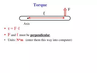
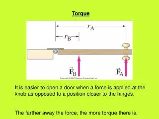
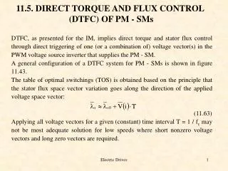
11.5. DIRECT TORQUE AND FLUX CONTROL (DTFC) OF PM - SMs. DTFC, as presented for the IM, implies direct torque and stator flux control through direct triggering of one (or a combination of) voltage vector(s) in the PWM voltage source inverter that supplies the PM - SM.

E N D
11.5. DIRECT TORQUE AND FLUX CONTROL (DTFC) OF PM - SMs DTFC, as presented for the IM, implies direct torque and stator flux control through direct triggering of one (or a combination of) voltage vector(s) in the PWM voltage source inverter that supplies the PM - SM. A general configuration of a DTFC system for PM - SMs is shown in figure 11.43. The table of optimal switchings (TOS) is obtained based on the principle that the stator flux space vector variation goes along the direction of the applied voltage space vector: (11.63) Applying all voltage vectors for a given (constant) time interval T = 1 / fc may not be most adequate solution for low speeds where short nonzero voltage vectors and long zero vectors are required. Electric Drives
Figure 11.43. DTFC for PM - SMs Electric Drives
Figure 11.44. Voltage vector selection for the first sector Electric Drives
The Ton time of nonzero voltage vectors may thus be made speed dependent provided Ton < T and Ton > Tmin (minimum conduction time allowable). On the other hand, if the “exact” position of stator flux is estimated, the required voltage vector may be predicted: (11.64) This time the space vector flux error (not only the amplitude error) is required. Once is computed, space vector modulation techniques may be applied to calculate the timings t1, t2 of the adjacent voltage vectors V(i), V(i+1) and of the zero voltage vector V0(V7): (11.65) (11.66) Smoother torque and flux control is obtained this way for given commutation frequency. Electric Drives
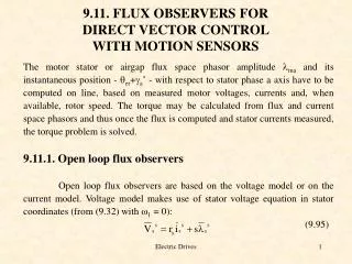
11.5.1. The stator flux and torque observer It is in general assumed that the stator currents ia, ib and voltages Va, Vb (or the d.c. link voltage Vd) are measured. Also an encoder provides both rotor position qr and speed feedback in all high performance drives [8]. The observers considered for IMs may be applied here also. Among the real practical ones we mention: the voltage - current, full order observers, Kalman filters and MRAS closed loop configurations. The voltage - current closed loop observer is presented here in some detail. The voltage model in stator coordinates is: (11.67) while the current model, in rotor coordinates, is; (11.68) The current in rotor coordinates is: (11.69) The stator flux is transformed back to stator coordinates as: (11.70) Electric Drives
The current model is influenced by parameter detuning (due to magnetic saturation) and by the position error but it works from zero speed (frequency). A combination of the two with a PI compensator is designed such that the current model is predominant at low speeds while the voltage model takes over at high speeds (figure 11.45). Figure 11.45. Voltage and current stator flux observer Electric Drives
The PI compensator provides for this discrimination. The frequency band for the transition is provided by an adequate choice of Ki and ti based on the given observer poles w1 and w2 [9], real and negative: (11.71) Typical values of w1 and w2 are: w1 = -(3 - 10)rad/s, w2 = -(3 - 10)|w1| Low speed and torque response for such a DTFC drive with sliding mode speed controller and the data: Ld = 4.1mH, Lq = 8.2mH, lPM = 0.2Wb, rs = 0.6W, J = 0.005Kgm2, p = 4pole pairs, fc = 10KHz, Vd = 200V, Temax = 12Nm are given in figure 11.46 [9]. The flux and torque hysteresis bands are 0.5% and 1% respectively. Figure 11.46. Low speed and torque transients with DTFC of PM - SM Electric Drives
11.6. SENSORLESS CONTROL OF PM - SMs Sensorless control is targeted for speed controlled drives where a less than 100 to 1 speed control range is required. It reduces hardware costs and improves mechanical reliability. High performance drives - for more than 100 to 1 speed range and for precision positioning - still require motion sensor feedback. Unfortunately vector control requires, even for speed control only, rotor position information. As for IM sensorless, control may be open loop or closed loop. Open loop (V / f) runs into problems of stability and it is adequate for low dynamics applications that require a maximum of 10 to 1 speed control range with good precision. Such drives need a damper cage on the rotor for improved stability (figure 11.2). Electric Drives
Feedforward torque compensation may be added to slightly improve the dynamics response. On the other hand closed loop sensorless PM - SM or BLDC motor drives require rotor and position observers to produce a 100 to 1 speed control range with fast dynamincs. Only closed loop sensorless control is approached in what follows. BLDC motor drives (with surface PM rotors, trapezoidal e.m.f. and rectangular current control) require special proximity (position) estimators. A classification of such estimators includes zero crossing of open phase e.m.f., back e.m.f. integration approach, third harmonic method, conduction time of diodes in the PWM inverter. Electric Drives
An example of a speed calculator is obtained with respect to figure 11.47. Figure 11.47. Rotor speed estimator for DTFC control of PM - SMs Electric Drives
where blocks A and B contain: (11.72) As the d - q flux angle d varies only in the first and fourth quadrants (ld 0, to avoid PM demagnetization) its estimation is straightforward. The derivatives required to estimate rotor speed are done based on sina and cosa derivatives properties in discrete form with T as the sampling time (figure 11.47). Notice that the speed estimator does not use inertia and, consequently, the motion equation has not been used for the scope. The latter may be used either to identify the load perturbation torque or somehow to correct the speed estimated from electrical equations. Electric Drives
11.6.1. Initial rotor position detection Most position and speed observers are not capable to detect the initial rotor position. Special starting methods or initial position identification, without moving the rotor to a known position, are required for safe, stable, starting. Initial rotor identification may be performed by the drive itself through sending short voltage vector signals V1, V3, V5 for a few microseconds until the phase currents reach a certain limit. From the time required for the current rising in the three cases, in case of interior PM rotors, the rather exact initial rotor position may be obtained based on the sinusoidal inductance - position dependence. On the other hand, for surface - PM rotor, additionally, negative m.m.f. is required for each position (V2, V4, V6) to find out in which 600 wide sector the rotor is placed based on the slight magnetic saturation (for positive m.m.f.) and desaturation of PMs (for negative m.m.f.) [11]. DTFC sensorless tends to selfstart from any position after a short lived oscillation as a certain voltage vector is applied until the flux surpasses the reference value for the first time. Electric Drives
11.7. RELUCTANCE SYNCHRONOUS MOTOR (RSM) DRIVES RSMs are characterized by the absence of rotor currents and, in rotor configurations. With multiple flux barriers (or anisotropic axially laminated (ALA), figure 11.48.a, b) high Ld / Lq rates provide for torque density (Nm/kg) power factor and efficiency comparable or slightly superior to induction motors. For Ld / Lq > 8 the RSM is fully competitive with the IM. The absence of rotor currents, especially, when an encoder is available for rotor position feedback, makes the RSM drive control notably simpler than for IMs. As ideally the core losses in the rotor are zero (in reality some harmonics flux loss curents exist) the RSM may work safely at low speeds and high torque, provided the stator is properly cooled. On the hand, the slightly fragile rotor limits the peripherial rotor speeds to, probably, 50 - 60m/s. So SRM might be considered from 100W up to 1 MW for speeds which limit the peripherial rotor speed to 50 - 60m/s. Electric Drives
Naturally, for conventionally laminated anisotropic rotors (figure 11.48.c) (Ld / Lq < 3), low power factor (about 0.45 - 0.50) low power, and higher peripherial speeds are acceptable. a.) Ld / Lq = 4 - 8 b.) Ld / Lq > (8 - 10) c.) Ld / Lq = 2 - 3 Figure 11.48. SRM rotors a.) with multiple flux barriers b.) ALA c.) conventional Electric Drives
11.7.1. RSM vector control principles The RSM may be considered as a nonlinear system with two entries; the stator flux and the torque Te (chapter 10, equations 10.116 - 10.117): (11.73) A PM in axis q (of lower inductance) has been included. For maximum torque / current, using (11.73) we obtain: (11.74) As (in - rated phase current, rms) to avoid heavy magnetic saturation, about half of rated torque may be expected when using this criterion. The maximum power factor criterion (rs = 0) is based on the definition: (11.75) Electric Drives
Finally we find (for ): (11.76) (11.77) (11.78) For maximum torque per flux: (11.79) Again for idl = idi: (11.80) or (11.81) Electric Drives
The highest torque may be obtained with the criterion of maximum torque / flux, but for lowest power factor (slightly lower than 0.707). The base speed wb, defined for maximum torque available, is thus: (11.82) For a more detailed analysis of steady state and transient torque capabilities of RSM see [12]. In essence, for servo drives without constant power (flux weakening) zone, and fast speed response, the criterion of maximum power factor may be used for steady state. For fast transients the maximum torque / flux approach is adequate. Electric Drives
Trajectories of id - iq currents and ld - lq fluxes for the three main optimal control strategies are shown in figure 11.49. Figure 11.49. Current and flux trajectories with speed increasing It has been shown that the influence of magnetic saturation (of Ld mainly) is small for maximum power factor control [13]. Electric Drives
Consequently the id, iq angle g: (11.83) should be made variable with torque (and speed). Same conditions may be met by working with flux linkage d - q angles (figure 11.49.b). In general, for wide (wmax / wb >2) constant power zones PMs in axis q are required [14]. For low speeds vector current control is more adequate while above base speed vector voltage control is better. A combination of the two is, perhaps, the practical solution for wide speed range control. Vector current control [15, 16], eventually combined with voltage decoupling in d - q orientation or in stator flux orientation [17], has been proposed. They are very similar to the corresponding methods developed for PM - SMs. In what follows we will only illustrate the vector control of RSM through a vector d - q current control system with id constant up to base speed wb and speed dependent above wb [18]. We will treat also direct torque and flux control DTFC [19]. Electric Drives
11.7.2. Indirect vector current control of RSM The indirect vector current control scheme (figure 11.50) is similar to that for the PM - SMs. Figure 11.50. Indirect vector current control of RSM Electric Drives
Either speed or position control may be performed. The reference magnetization current id* is constant up to base speed wb and decreases inversely with speed above wb. Let us introduce some details on the sliding mode (SM) speed controller simulation and test results. The SM speed controller output produces the reference torque current iq* and the simplest control law is: (11.84) where wh is the hysteresis band of the controller and sw is the SM functional: (11.85) Electric Drives
Besides meeting the conditions of touching the straight line sw = 0 (in the state space plane) we need to know Kpw and Kdw. To do so we admit that iq varies linearly in time and the targeted speed wr* is reached after sw changes sign at least once (figure 11.51): Figure 11.51. Ideal transients (constant id, linear variation of iq) The ratio Kw = Kdw / Kpw is to be determined first. If for t = 0, sw = 0, for no - load, equation (11.85) yields: (11.86) Electric Drives
where Te is the torque, J - inertia and p - pole pairs. If iq varies linearly the torque Te does the same thing (id = const) and, from t0 to t0+t1 (figure 11.51), we have: (11.87) From (11.87), through integration, we have: (11.88) Comparing with (11.86) yields: (11.89) A good approximation could be t1 = Lq / 2rs and thus: (11.90) Electric Drives
For an RSM with data: 2p = 6, Lq = 24mH, Ld = 88mH for id* = 3A, rs = 0.8W, J = 0.0157kgm2, V0 = 80V, fc = 5kHz, for idm* = 3A and iqm* = 5A, Kpw = 5, Kw = 7.5x10⁻³s, Kdw = 0.01s. wh = 5rad/s, Jmax = 5J, Kpq = 5, Kdq = 0.75, qh = 3p/50rad. The digital simulation and test results are shown for comparison in figures ((11.52) - (11.53)). Figure 11.52. Steady state phase current a.) digital simulation b.) test results Notice that the acceleration decreases above 500rpm as step - wise id decrease with speed is performed (figure 11.53.a). Electric Drives
Figure 11.53. Step speed responses a.) digital simulation b.) test results Figure 11.54. Positioning responses (calculated) a.) rated inertia J b.) 5J As the position SM controller is designed for 5J there is no wonder that the responses for J and 5J do not differ notably (figure 11.54). This kind of robustness with the elimination of overshoot and with fast response are intrinsic merits of SM controllers. Electric Drives
11.7.3. Direct torque and flux control (DTFC) of RSM The DTFC of RSM is similar to that of PM - SM. The basic configuration is shown on figure 11.55. Figure 11.55. Direct torque and flux control of RSM 1. with motion sensor 2. sensorless Electric Drives
The flux and torque observers are paramount to DTFC. A speed observer (estimator) is required, in addition, for sensorless control (figure 11.55). The rationale and the table of optimal switchings developed for PM - SMs remain valid here (section 11.5). Only the flux and torque observer bears some pecularities in the sense that the PM flux is dropped from axis d (figure 11.45) and eventually subtracted from axis q (if a PM along axis q is added). Also Ld > Lq. Digital simulation results [14] with DTFC are now presented for a 1.5kW, 2 pole motor with Ld = 140.77mH, Lq = 7.366mH rs = 0.955W, J = 2.5x10⁻³kgm2, switching frequency fc = 15kHz (figure 11.57). The time constant is ts in the speed SM controller functional sw: (11.91) ts = 1.2ms. Electric Drives
Figure 11.56. Speed step response with step load 3Nm at t1 = 60ms. Figure 11.57. Low speed step response Fast speed response without overshoot is evident both for low and high speeds (figure 11.56 - 11.57). Electric Drives
11.7.4. Sensorless control of RSM Although sensorless control of RSM may be open loop (V / f or scalar) eventually with some load torque angle compensation (figure 11.2), closed loop sensorless vector control is favored due to superior dynamic performance and wider speed control range (100 to 1). For vector sensorless control both rotor position qr and speed wr have to be estimated (or observed). Various methods to do this have been proposed; (for a collection of papers on the subject see [10], section 3). They are based on: the combined voltage and current observer, current slope, inductance measurements, third flux harmonics, extension of the zero crossing of phase current etc. We mention here only the voltage and current model for flux and torque observer (figure 11.45 - with lPM = 0 and Ld > Lq). We have to add to it the rotor speed estimator (figure 11.47) for rotor speed and a position feedback (figure 11.58). Electric Drives
Figure 11.58. Position, speed, flux and torque observer for RSM (wide speed range) Electric Drives
The rather involved observer ( ) in figure 11.58 is required to determine the rotor position used here only in the current model part of the flux observer for the rotor speed , and, finally for flux and torque computation. Also in figure 11.58: (11.92) If Ld >> Lq the whole observer is only loosely dependent on machine parameters. Still, corrections for stator resistance variation due to temperature and Ld and Lq variation with stator currents id and iq might be added for higher immunity to parameter variations. As expected, the above observer may be used also for most vector control sensorless schemes. Electric Drives
Wide constant power speed range has been demonstrated with PM - SMs or RSMs with PMs. • The unity power level constant power speed range Kcpr is [5, 20]: • (11.93) • where wc is the critical (zero torque) speed in relative units (per base speed wb), e0 is the PM (no load) voltage in relative units (per rated (maximum) voltage), xd is the d axis reactance in relative units. • If we consider that for RSM the d axis is along the low permeance path as for the PM - SMs (change of places of d and q axis) wc is valid also for RSM with PMs. • A theoretically infinite constant power zone (11.93) is obtained for: • (11.94) • however, at low levels of power. Electric Drives
Condition (11.93) is met in conventional PM - SMs with e0 > 0.5 in general to retain some acceptable power factor and with smaller e0 (e0 < 0.3) for RSMs with low costs PM (in axis q) and good power factor. Constant power zone requirements are in some conflict with high torque requirements in steady state and transients below base speed wb. Electric Drives