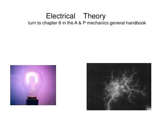
Electrical Theory
Electrical Theory turn to chapter 8 in the A & P mechanics general handbook. All matter can be defined as anything that has mass (weight),. So matter is everything that exists.

Electrical Theory
E N D
Presentation Transcript
Electrical Theory turn to chapter 8 in the A & P mechanics general handbook
All matter can be defined as anything that has mass (weight), So matter is everything that exists
The smallest particle of matter is called an atom which is used to make up a molecule. Water for example is 2 hydrogen atoms and 1 oxygen atom
Within these atoms we have electrons rotating around protons electron is an negative charge of electricity protons which are a positive charge Animation click
The atom is considered neutral if the electrons and the protons are equal If there are more electrons (negative) than protons then the atom has a negative charge. If there are more protons than electrons it is said to have a positive charge
When objects have the same charge they will repel (pull away) each other, but if they have opposite charges they will be attracted to each other.
Electrons flow from a negative point to a positive point that is called current flow. CLICK It flows because of the difference in pressure between the 2 points.
This can be compared to the flow of water between 2 tanks that have different pressures (fig 8-12). When the water in the 2 tanks is the same the flow will stop.
-If one tank had 10 psi in it and the other had 2 psi, a difference of 8 psi would exist. -The same is true in an electrical circuit as the potential difference between 2 points is measured in 8 volts.
Direct Current (DC) is when the electrons move in one direction only AC or alternating current is when the flow is alternating from one direction to another
Using a garden hose analogy the current would be similar to the moving water in the hose. Click for flow animation
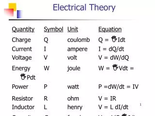
Resistance is the ability of an electrical conductor to restrict the flow of electrons
The unit used to measure resistance is called an ohm . It is said that an ohm is the resistance needed to limit 1 amp to flow from a charge of 1 volt
The 4 factors effecting resistance are 1) the material 2) The length {see fig 8-14}
3) cross sectional area ( wire gauge) 4) Temperature { usually increase in the temp of the conductor means an increase in the resistance
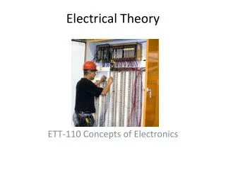
The basics of an electrical circuit are 1) a power source (electrical pressure-battery) 2) Resistance in the form of an energy consuming device
- With out resistance in the circuit the conductors would become overheated and burn
-Variable resisters (fig 8-34) are used when the circuit is in operation. Where would we see this in operation around the house?
Common symbols for a generator are Fig 8-19 shows the symbols for a single cell battery and a three cell battery. Battery symbols always include 1) a short vertical line representing a negative terminal, 2) a longer line for the positive terminal
- fig 8-26 shows a typical view of a fuse which is installed in most circuits to protect it against excessive current flow. Fig 8-27 shows an open switch and a closed switch
A typical ground symbol is shown in fig 8-28 Notice how the ammeter and voltmeter are show as they need to placed within a circuit
- Pg 287 shows several series circuit schematics. Fig 8-54 shows the current flowing from negative to positive ( there are 2 schools of thought on this) through a resistance. 8-55 shows a proper circuit with a battery , switch, load & fuse.
- The figures on pg 276 show: - A series circuit where the voltage is added together and the current stays the same - A parallel circuit where the voltage stays the same and the current is added together
By placing your thumb over the unknown value in the ohms law triangle . The formula to solve becomes apparent In this case by covering “I” (for amps). The formula volts ÷ resistance will solve for how many amps will be drawn in this circuit
28.8 V 0.48 Amp 43.2 V 0.48 Amp 48 V 0.48 Amp 0.48 Amp 250 Ω
120 volts 3.0 amps 120 volts 2.4 amps 120 volts 2.0 amps 7.4 amps 16.2 Ω