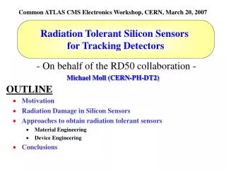
Michael Moll (CERN-PH-DT)
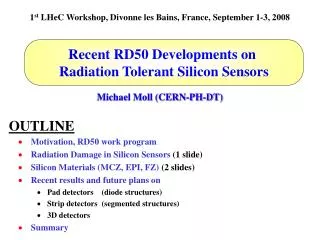
1 st LHeC Workshop, Divonne les Bains, France, September 1-3, 2008. Recent RD50 Developments on Radiation Tolerant Silicon Sensors. OUTLINE. Motivation, RD50 work program Radiation Damage in Silicon Sensors (1 slide) Silicon Materials (MCZ, EPI, FZ) (2 slides)

Michael Moll (CERN-PH-DT)
E N D
Presentation Transcript
1st LHeC Workshop, Divonne les Bains, France, September 1-3, 2008 Recent RD50 Developments on Radiation Tolerant Silicon Sensors OUTLINE • Motivation, RD50 work program • Radiation Damage in Silicon Sensors (1 slide) • Silicon Materials (MCZ, EPI, FZ) (2 slides) • Recent results and future plans on • Pad detectors (diode structures) • Strip detectors (segmented structures) • 3D detectors • Summary Michael Moll (CERN-PH-DT)
Motivation for R&D on Radiation Tolerant Detectors: Super - LHC 5 years 10 years 2500 fb-1 500 fb-1 • LHC upgradeLHC (2008) L = 1034cm-2s-1f(r=4cm) ~3·1015cm-2 • Super-LHC (2018 ?) L = 1035cm-2s-1f(r=4cm) ~1.6·1016cm-2 • LHC (Replacement of components)e.g. - LHCb Velo detectors - ATLAS Pixel B-layer 5 SLHC compared to LHC: • Higher radiation levels Higher radiation tolerance needed! • Higher multiplicity Higher granularity needed! Power Consumption ?Cooling ?ConnectivityLow mass ?Costs ? Need for new detectors & detector technologies Michael Moll – 1st LHeC Workhsop, Divonne, 1-3 September 2008 -2-
Signal degradation for LHC Silicon Sensors Note: Measured partly under different conditions! Lines to guide the eye (no modeling)! Pixel sensors: max. cumulated fluence for LHC Strip sensors: max. cumulated fluence for LHC Michael Moll – 1st LHeC Workhsop, Divonne, 1-3 September 2008 -3-
Signal degradation for LHC Silicon Sensors Note: Measured partly under different conditions! Lines to guide the eye (no modeling)! Pixel sensors: max. cumulated fluence for LHC andSLHC SLHC will need more radiation tolerant tracking detector concepts! Strip sensors: max. cumulated fluence for LHC andSLHC Michael Moll – 1st LHeC Workhsop, Divonne, 1-3 September 2008 -4-
Radiation Damage in Silicon Sensors Influenced by impuritiesin Si – Defect Engineeringis possible! Same for all tested Silicon materials! Can be optimized! • Two general types of radiation damage: Bulk (Crystal) damagedue to Non Ionizing Energy Loss (NIEL) - displacement damage, built up of crystal defects – • Change of effective doping concentrationtype inversion, higher depletion voltage, under-depletion loss of active volume decrease of signal, increase of noise • Increase of leakage current increase of shot noise, thermal runaway, power consumption… • Increase of charge carrier trapping loss of charge Surface damagedue to Ionizing Energy Loss (IEL) - accumulation of positive in the oxide (SiO2) and the Si/SiO2 interface – interstrip capacitance, breakdown behavior, … • Impact on detector performance and Charge Collection Efficiency (depending on detector type and geometry and readout electronics!) Signal/noise ratio is the quantity to watch Michael Moll – 1st LHeC Workhsop, Divonne, 1-3 September 2008 -5-
RD50 approaches to develop radiation harder tracking detectors • Material Engineering -- Defect Engineering of Silicon • Understanding radiation damage • Macroscopic effects and Microscopic defects • Simulation of defect properties & kinetics • Irradiation with different particles & energies • Oxygen rich Silicon • DOFZ, Cz, MCZ, EPI • Oxygen dimer & hydrogen enriched Silicon • Influence of processing technology • Material Engineering-New Materials (work concluded) • Silicon Carbide (SiC), Gallium Nitride (GaN) • Device Engineering (New Detector Designs) • p-type silicon detectors (n-in-p) • thin detectors • 3D detectors • Simulation of highly irradiated detectors • Semi 3D detectors and Stripixels • Cost effective detectors • Development of test equipment and measurement recommendations Related Works – Not conducted by RD50 • “Cryogenic Tracking Detectors” (CERN RD39) • “Diamond detectors” (CERN RD42) • Monolithic silicon detectors • Detector electronics Michael Moll – 1st LHeC Workhsop, Divonne, 1-3 September 2008 -6-
Poly silicon RF Heating coil Single crystal silicon Float Zone Growth Silicon Growth Processes • Czochralski Silicon (CZ) • Floating Zone Silicon (FZ) • The growth method used by the IC industry. • Difficult to producevery high resistivity Czochralski Growth • Epitaxial Silicon (EPI) • Chemical-Vapor Deposition (CVD) of Si • up to 150 mm thick layers produced • growth rate about 1mm/min • Basically all silicon detectors made out of high resistivity FZ silicon Michael Moll – 1st LHeC Workhsop, Divonne, 1-3 September 2008 -7-
standardfor particledetectors used for LHC Pixel detectors “new”siliconmaterial Silicon Materials under Investigation • DOFZ silicon- Enriched with oxygen on wafer level, inhomogeneous distribution of oxygen • CZ/MCZ silicon- high Oi (oxygen) and O2i (oxygen dimer) concentration (homogeneous) - formation of shallow Thermal Donors possible • Epi silicon- high Oi , O2i content due to out-diffusion from the CZ substrate (inhomogeneous) - thin layers: high doping possible (low starting resistivity) • Epi-Do silicon - as EPI, however additional Oi diffused reaching homogeneous Oi content Michael Moll – 1st LHeC Workhsop, Divonne, 1-3 September 2008 -8-
RD50 Test Sensor Production Runs (2005-2008) • Recent production of Silicon Strip, Pixel and Pad detectors (non exclusive list): • CIS Erfurt, Germany • 2005/2006/2007 (RD50): Several runs with various epi 4” wafers only pad detectors • CNM Barcelona, Spain • 2006 (RD50): 22 wafers (4”), (20 pad, 26 strip, 12 pixel),(p- and n-type),(MCZ, EPI, FZ) • 2006 (RD50/RADMON): several wafers (4”), (100 pad), (p- and n-type),(MCZ, EPI, FZ) • HIP, Helsinki, Finland • 2006 (RD50/RADMON): several wafers (4”), only pad devices, (n-type),(MCZ, EPI, FZ) • 2006 (RD50) : pad devices, p-type MCz-Si wafers, 5 p-spray doses, Thermal Donor compensation • 2006 (RD50) : full size strip detectors with 768 channels, n-type MCz-Si wafers • IRST, Trento, Italy • 2004 (RD50/SMART): 20 wafers 4” (n-type), (MCZ, FZ, EPI), mini-strip, pad 200-500mm • 2004 (RD50/SMART): 23 wafers 4” (p-type), (MCZ, FZ), two p-spray doses 3E12 amd 5E12 cm-2 • 2005 (RD50/SMART): 4” p-type EPI • 2008 (RD50/SMART): new 4” run • Micron Semiconductor L.t.d (UK) • 2006 (RD50): 4”, microstrip detectors on 140 and 300mm thick p-type FZ and DOFZ Si. • 2006/2007 (RD50): 93 wafers, 6 inch wafers, (p- and n-type), (MCZ and FZ), (strip, pixel, pad) • Sintef, Oslo, Norway • 2005 (RD50/US CMS Pixel) n-type MCZ and FZ Si Wafers • Hamamatsu, Japan [ATLAS ID project – not RD50] • In 2005 Hamamatsu started to work on p-type silicon in collaboration with ATLAS upgrade groups (surely influenced by RD50 results on this material) • M.Lozano, 8th RD50 Workshop, Prague, June 2006 • A.Pozza, 2nd Trento Meeting, February 2006 • G.Casse, 2nd Trento Meeting, February 2006 • D. Bortoletto, 6th RD50 Workshop, Helsinki, June 2005 • N.Zorzi, Trento Workshop, February 2005 • H. Sadrozinski, rd50 Workshop, Nov. 2007 Hundreds of samples (pad/strip/pixel) recently produced on various materials (n- and p-type). Michael Moll – 1st LHeC Workhsop, Divonne, 1-3 September 2008 -9-
FZ, DOFZ, Cz and MCz Silicon 24 GeV/c proton irradiation (n-type silicon) • Strong differences in Vdep • Standard FZ silicon • Oxygenated FZ (DOFZ) • CZ siliconand MCZ silicon • Strong differences in internalelectric field shape(type inversion in FZ, no type inversion in MCZ silicon, double junction effects,…) • Different impact on pad and strip detector operation! • e.g.: a lower Vdep or |Neff| does not necessarily correspond to a higher CCE for strip detectors (see later)! • Common to all materials (after hadron irradiation): • reverse current increase • increase of trapping (electrons and holes) within ~ 20% Michael Moll – 1st LHeC Workhsop, Divonne, 1-3 September 2008 -10-
Advantage of non-inverting materialp-in-n detectors (schematic figures!) Fully depleted detector(non – irradiated): Michael Moll – 1st LHeC Workhsop, Divonne, 1-3 September 2008 -11-
Advantage of non-inverting materialp-in-n detectors (schematic figures!) non inverted • non-inverted, under-depleted: • Limited loss in CCE • Less degradation with under-depletion Be careful, this is a very schematic explanation, reality is more complex ! Fully depleted detector(non – irradiated): heavy irradiation inverted • inverted to “p-type”, under-depleted: • Charge spread – degraded resolution • Charge loss – reduced CCE Michael Moll – 1st LHeC Workhsop, Divonne, 1-3 September 2008 -12-
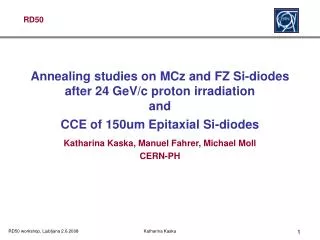
Epitaxial silicon - Annealing 50 mm thick silicon detectors:- Epitaxial silicon (50Wcm on CZ substrate, ITME & CiS) - Thin FZ silicon (4KWcm, MPI Munich, wafer bonding technique) [E.Fretwurst et al.,RESMDD - October 2004] • Thin FZ silicon: Type inverted, increase of depletion voltage with time • Epitaxial silicon: No type inversion, decrease of depletion voltage with time No need for low temperature during maintenance of SLHC detectors! Michael Moll – 1st LHeC Workhsop, Divonne, 1-3 September 2008 -13-
Device engineering (p-type silicon)p-in-n versus n-in-p (or n-in-n) detectors p+ strip readout (p-in-n)after high fluences: n+ strip readout (n-in-p or n-in-n)after high fluences: n+on-p p+on-n • n-on-p silicon, under-depleted: • Limited loss in CCE • Less degradation with under-depletion • Collect electrons (fast) • p-on-n silicon, under-depleted: • Charge spread – degraded resolution • Charge loss – reduced CCE Be careful, this is a very schematic explanation,reality is more complex ! Michael Moll – 1st LHeC Workhsop, Divonne, 1-3 September 2008 -14-
n-in-p microstrip detectors • n-in-p microstrip p-type FZ detectors (Micron, 280 or 300mm thick, 80mm pitch, 18mm implant ) • Detectors read-out with 40MHz (SCT 128A) Signal(103 electrons) Fluence(1014 neq/cm2) [G.Casse, RD50 Workshop, June 2008] • CCE: ~7300e (~30%) after ~ 11016cm-2 800V • n-in-p sensors are strongly considered for ATLAS upgrade(previously p-in-n used) Michael Moll – 1st LHeC Workhsop, Divonne, 1-3 September 2008 -15-
no reverse annealing in CCE measurementsfor neutron and proton irradiated detectors n-in-p microstrip detectors • n-in-p microstrip p-type FZ detectors (Micron, 280 or 300mm thick, 80mm pitch, 18mm implant ) • Detectors read-out with 40MHz (SCT 128A) Signal(103 electrons) Fluence(1014 neq/cm2) [G.Casse, RD50 Workshop, June 2008] • CCE: ~7300e (~30%) after ~ 11016cm-2 800V • n-in-p sensors are strongly considered for ATLAS upgrade(previously p-in-n used) Michael Moll – 1st LHeC Workhsop, Divonne, 1-3 September 2008 -16-
n-columns p-columns wafer surface PLANAR 3D p+ p+ p+ n+ 50 mm - 300 mm n-type substrate - - - - - - - - - + + + + + + + + + + Introduced by: S.I. Parker et al., NIMA 395 (1997) 328 3D detector - concept • “3D” electrodes: - narrow columns along detector thickness, - diameter: 10mm, distance: 50 - 100mm • Lateral depletion: - lower depletion voltage needed - thicker detectors possible - fast signal - radiation hard Michael Moll – 1st LHeC Workhsop, Divonne, 1-3 September 2008 -17-
TEOS Poly p+ n- Junction 10mm Double-Sided 3D detectors • Advantages against standard 3D:- Less complicated (expensive) process (??) - No wafer bonding - p+ and n+ columns accessed from opposite surfaces • Disadvantages (?) :- lower field region below/above columns • Under processing at CNM, Barcelona RD50 collaborative work (CNM, Glasgow, Valencia, …) • Successful process evaluation runs:- etching of holes with aspect ratio 25:1 (10 mm diameter, 250 mm depth)- polysilicon deposit, doping, TEOS, .. [G.Fleta, RD50 Workshop, June 2007] • 4” wafer with Pad, Strip (short and long, 80mm pitch) and Pixel (ATLAS, Medipix2, Pilatus) structures processed at CNM, Barcelona - p-in-n and n-in-p wafers under test now • Further processing at FBK, Trento and IceMOS, Belfast Michael Moll – 1st LHeC Workhsop, Divonne, 1-3 September 2008 -18-
Comparison of measured collected charge on different radiation-hard materials and devices • In the following: Comparison of collected charge as published in literature • Be careful: Values obtained partly under different conditions !! • irradiation • temperature of measurement • electronics used (shaping time, noise) • voltage applied to sensor • type of device – strip detectors or pad detectors This comparison gives only an indication of which material/technology could be used, to be more specific, the exact application should be looked at! • Remember: The obtained signal has still to be compared to the noise !! Michael Moll – 1st LHeC Workhsop, Divonne, 1-3 September 2008 -19-
Silicon materials for Tracking Sensors Note: Measured partly under different conditions! Lines to guide the eye (no modeling)! • Signal comparison for various Silicon sensors Michael Moll – 1st LHeC Workhsop, Divonne, 1-3 September 2008 -20-
Silicon materials for Tracking Sensors Note: Measured partly under different conditions! Lines to guide the eye (no modeling)! • Signal comparison for various Silicon sensors Michael Moll – 1st LHeC Workhsop, Divonne, 1-3 September 2008 -21-
Silicon materials for Tracking Sensors Note: Measured partly under different conditions! Lines to guide the eye (no modeling)! • Signal comparison for various Silicon sensors Michael Moll – 1st LHeC Workhsop, Divonne, 1-3 September 2008 -22-
Silicon materials for Tracking Sensors Note: Measured partly under different conditions! Lines to guide the eye (no modeling)! • Signal comparison for various Silicon sensors LHC SLHC n-in-p technology should be sufficient for Super-LHC at radii presently (LHC) occupied by strip sensors highest fluence for strip detectors in LHC: The used p-in-n technology is sufficient Michael Moll – 1st LHeC Workhsop, Divonne, 1-3 September 2008 -23-
Silicon materials for Tracking Sensors Note: Measured partly under different conditions! Lines to guide the eye (no modeling)! • Signal comparison for various Silicon sensors • At a fluence of ~ 1015 neq/cm2 all planar sensors loose sensitivity: on-set of trapping ! • No obvious material for innermost pixel layers: • Are 3-D sensors an option ?? (decoupling drift distance from active depth) • Develop detectors that can live with very small signals ?? or regularly replace inner layers ?? Michael Moll – 1st LHeC Workhsop, Divonne, 1-3 September 2008 -24-
Silicon materials for Tracking Sensors Note: Measured partly under different conditions! Lines to guide the eye (no modeling)! • Signal comparison for various Silicon sensors See talk of Norbert Wermes for S/N scaling • At a fluence of ~ 1015 neq/cm2 all planar sensors loose sensitivity: on-set of trapping ! • No obvious material for innermost pixel layers: • Are 3-D sensors an option ?? (decoupling drift distance from active depth) • Develop detectors that can live with very small signals ?? or regularly replace inner layers ?? Michael Moll – 1st LHeC Workhsop, Divonne, 1-3 September 2008 -25-
p-type FZ Silicon Sensors Note: Measured partly under different conditions! Lines to guide the eye (no modeling)! • Higher voltage helps! 1700V 800V 500V Data: G.Casse et al. (Liverpool) [RD50 06/2008 & VERTEX 2008]and I.Mandic et al. (Ljubljana) [RD50 06/2008] • Which voltage can be applied? Michael Moll – 1st LHeC Workhsop, Divonne, 1-3 September 2008 -26-
Strip detectors – MCZ silicon • Gianluigi Casse (Liverpool) [RD50 Workshop – June 2008]: “Charge Collection Measurements on MICRON RD50 sensors” MCZn-in-n FZ sensorsn-in-nandn-in-p p-in-n sensors (MCZ, FZ) Michael Moll – 1st LHeC Workhsop, Divonne, 1-3 September 2008 -27-
“Mixed Irradiations” n-type MCZ Gianluigi Casse (Liverpool) [VERTEX 2008] • Mixed irradiations performed with • (neutrons only) up to 1x10¹⁵ neutrons • (mixed) 5x10¹⁴ neutrons plus 5x10¹⁴ protons (1 MeV equivalent fluence) • MCZ (n-in-n) Mixed Irradiation:Proton damage “compensates” part of neutron damage (Neff) Excellent performance! Neutron Irradiation: Higher CCE than FZ silicon • FZ (n-in-n) FZ (n-in-p) Comment: NIEL scaling very strongly violated ! 500V Michael Moll – 1st LHeC Workhsop, Divonne, 1-3 September 2008 -28-
Summary • Wide range of silicon materials under investigation within RD50 • Floating Zone (FZ), Magnetic Czochralski (MCZ), Epitaxial (EPI) silicon • n- and p-type silicon with different thickness ranging from 25 to 300 mm • Some materials do not ‘type-invert’ under proton irradiation (n-type MCZ, EPI) Very complex internal electric field structure (double junction effects) • Segmented detectors at high fluences (Φ > 1015cm-2): • Collection of electrons at electrodes essential: Use n-in-p or n-in-n detectors! • Good radiation tolerance of n-in-p detectors and ‘CCE immunity’ against reverse annealing • MCZ and FZ p-type show similar results • MCZ n-type (n-in-n) shows excellent results (would need double sided processing) • 3D detectors • Single type column 3D – processed, irradiated, analyzed : Not radiation tolerant (as expected) – However, ‘paved the way’ for double column 3D detectors • Production of Double Sided and Full 3D detectors under way in several facilities (IRST, CNM, Sintef, IceMOS,…). First unirradiated devices characterized. • Not reported on: • Defect studies: “WODEAN” - Massive work program under way using C-DLTS, I-DLTS, TSC, PITS, TCT, FTIR, EPR, PL, PC, CV, IV, .. methods – (~10 RD50 Institutes) – about 250 detectors irradiated with neutrons for a first experiment. Further information: http://cern.ch/rd50/ Michael Moll – 1st LHeC Workhsop, Divonne, 1-3 September 2008 -29-
Spare Michael Moll – 1st LHeC Workhsop, Divonne, 1-3 September 2008 -30-
Development of Radiation Hard Semiconductor Devices for High Luminosity Colliders Approved as CERN R&D project “RD50” in June 2002 Presently :257 Members from 49 Institutes 40 European and Asian institutesBelarus (Minsk), Belgium (Louvain), Czech Republic (Prague (3x)), Finland (Helsinki), Germany (Dortmund, Erfurt, Freiburg, Hamburg, Karlsruhe, Munich), Italy (Bari, Bologna, Florence, Padova, Perugia, Pisa, Torino, Trento), Lithuania (Vilnius), Netherlands (NIKHEF), Norway (Oslo (2x)), Poland (Warsaw(2x)), Romania (Bucharest (2x)),Russia (Moscow, St.Petersburg), Slovenia (Ljubljana), Spain (Barcelona, Valencia), Switzerland (CERN, PSI), Ukraine (Kiev), UnitedKingdom (Exeter, Glasgow, Lancaster, Liverpool) 8 North-American institutesCanada (Montreal), USA (BNL, Fermilab, New Mexico, Purdue, Rochester, Santa Cruz, Syracuse) 1 Middle East instituteIsrael (Tel Aviv) Detailed member list: http://cern.ch/rd50 Michael Moll – 1st LHeC Workhsop, Divonne, 1-3 September 2008 -31-
Epitaxial SiC “A material between Silicon and Diamond” • Wide bandgap (3.3eV) • lower leakage current than silicon • Signal:Diamond 36 e/mmSiC 51 e/mmSi 89 e/mm • more charge than diamond • Higher displacement threshold than silicon • radiation harder than silicon (?) Michael Moll – 1st LHeC Workhsop, Divonne, 1-3 September 2008 -32-
The electric field after irradiation from G.Casse Michael Moll – 1st LHeC Workhsop, Divonne, 1-3 September 2008 -33-
The electric field after irradiation Michael Moll – 1st LHeC Workhsop, Divonne, 1-3 September 2008 -34-
CNM – 3D devices • Chris Parkes (Glasgow University): “3D detector testing” • CNM 3D devices (strip) • Glasgow MIP test setup(Sr90, Beetle Chip, analogue,25ns) • Sensor DC coupled to chip • 100pA/strip (2pA/hole) • 10 pF/strip • less charge sharing than in planar observed • planar 38% single strip • 3D 84% single strip Michael Moll – 1st LHeC Workhsop, Divonne, 1-3 September 2008 -35-