Download

1 / 40
400 likes | 484 Vues
Explore the reliability guidelines and implementation in superconducting linac design for Accelerator-Driven Systems (ADS), focusing on fault tolerance, redundancy, and system availability. Discuss the challenges and solutions for ensuring high reliability in ADS linac components. Learn about the comprehensive reliability exploration activities and study results from the Eurotrans program. Discover the objectives, qualitative assessments, and deliverables related to reliability in high-power proton accelerators for ADS applications.

E N D
CARE-HHH-APD BEAM’07 CERN, 1-5 October 2007 Fifth International Workshop on the Utilisation and Reliability of High Power Proton Accelerators Mol, Belgium, 6-9 May 2007 Work supported by the EURATOM 6° framework program of the EC, under contract FI6W-CT-2004-516520 Reliability of a s.c. linac from the ADS perspective Paolo Pierini, INFN Milano LASA with many contribution from DM1/WP1.3-Accelerator (IPNO/CEA/IBA/IAP/INFN) and ENEA Revised version for:
31 Research Agencies and Industries 16 Universities in an association EUROTRANS EUROPEAN RESEARCH PROGRAMME FOR THE TRANSMUTATION OF HIGH LEVEL NUCLEAR WASTE IN AN ACCELERATOR DRIVEN SYSTEM In the 6° Framework Programme of EC (2005-2008) Expands 5° FP PDS-XADS Project (2001-2004) 4 year research budget 42.3 M€ (23 M€ from EU funds)
Overall EUROTRANS Goals • Work towards a European Transmutation Demonstration (ETD) in a step-wise manner • Advanced design of a 50 to 100 MWth eXperimental facility demonstrating the technical feasibility of Transmutation in an Accelerator Driven System (XT-ADS) • realization in a short-term, say about 10 years • Generic conceptual design (several 100 MWth) of a modular European Facility for Industrial Transmutation (EFIT) • realisation in the long-term
FP Design Concepts Objectives FP52001-2004 MYRRHA (Pb-Bi) 50 MWth < 500 W/cm (peak) multi batch loading XADS Demonstration of technologicalfeasibility of an ADS system XADS (Pb-Bi) 80 MWth 110 W/cm single batch loading XADS (Gas) 80 MWth 250 W/cm single batch loading European Transmutation Demonstration short-term demonstration long-term demonstration ETD / XT-ADS 50 - 100 MWth 300 - 350 W/cm (~700 W/cm³) multi batch loading XT-ADS Short-term Demonstration of transmutation on a sizable scale and of the ADS behaviour FP62005-2008 ETD / EFIT Several 100 MWth 250 - 300 W/cm (450-650 W/cm³) multi batch loading EFIT Long-term Transmutation on an industrial scale Evolution of the concept
Accelerator workpackage • Accelerator design performed in the PDS-XADS program • Choice of superconducting linac • Modular: same concept for Prototype and Industrial scale
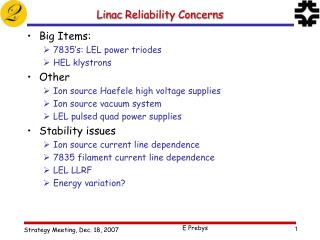
Issues for an ADS driver • Specific challenges for ADS: • High reliability and availability • Less than a few unexpected beam shutdowns per year • trips longer than 1 s duration induce stresses on fuel and assembly • Component design and operation following the reliability-oriented procedures used in the nuclear reactor community • strong design • planning of redundance and fault tolerance capabilities • High power CW operation • But with the possibility for beam holes (200 μs) at low duty cycle for on-line reactivity measurements of the subcritical assembly • For every linac component (in the high-energy, mid-energy and low-energy sections) in the EUROTRANS program a prototype will be designed, built and tested
How reliability has been implemented • Reliability guidelines extensively used in the linac design • Derating • Redundancies • Fault tolerance • Provide redundancy in the most critical items • Source, RFQ, low energy stage • Achieved by injector duplication! • Handle the “natural” redundancy in the superconducting linac • A SC linac has a high degree of modularity • The whole beamline is an array of nearly identical “periods” All components are derated with respect to technological limitations • A high degree of fault tolerance with respect to cavity/magnets can be expected in the SC linac • Implies a reliable and sophisticated digital RF control system with preset set points for implementation
The reliability exploration activity • Starting with FP5 PDS-XADS we have started developing a qualitative FMEA + a lumped-component reliability model of the driver superconducting linac • preliminary “parts count” assessment presented at HPPA4 • Extended study to variety of linac configurations • L.B., P.P., Rel. Eng. System Safety92 (2007) 449-463 • concentrate on design issues rather than component data • fault tolerance implementation • missing of a exhaustive and representative reliability parameter database • FP6 EUROTRANS assumes the same linac layout • Study extended to show sensitivity to component reliability characteristics
Three project deliverables dedicated to reliability assessments Qualitative FMEA RBD analysis Assessment of (lack of) existing MTBF database for components Identification of redundant and fault tolerant linac configurations intended to provide nominal reliability characteristics Outcome of FP5 PDS-XADS activities
Definition of the reliability objectives • Define a Mission Time, the operation period for which we need to carry out estimations • Depends on design of subcritical assembly/fuel cycle • big difference w.r.t. HEP context, no weekly maintenance • Define parameter for reliability goal • Fault Rate, i.e. Number of system faults per mission • Availability • No concern on R parameter at mission time • R is the survival probability • relevant for mission critical (non repairable environments, satellites!) • Provide corrective maintenance “rules” on elements • Components in the accelerator tunnel can be repaired only during system halt • Personnel protection issues in radiation areas • Components in shielded areas can be repaired immediately
Reliability goal • Assumed XT-ADS • 3 months of continuous operation with < 3 trips per period • 1 month of long shutdown • 3 operation cycles per year • 10 trips per year (i.e. beam interruptions longer than a second) • no constraints on R
RAMS • Baseline idea: use a commercial available RAMS tool for formal accelerator reliability estimations • Powerful RBD analysis • Montecarlo evalutation • Elaborated connection configurations • Hot parallelism • Standby parallelism • Warm parallelism • “k/n” parallelism • Many options for maintenance schemes and actions (both preventive & corrective, “kludge fixes”, etc.) • Eg: fix when system fails or fix when component fail (it’s the same only for series connection) • can easily account for maintenance cost and repair and spare logistics • Not used at all in accelerator community (or at least very rarely!)
What kind of faults are in component MTBF? • MTBF means only random failure events • Every failure that is highly predictable should get out of the MTBF estimations, and goes into the (preemptive) maintenance analysis • eg. Components wear out, failures related to bad design, Aging (if we perform a constant failure rate analysis) • Example: CRT Monitor in a RBD block • MTBF of 100.000 h • But we know that CRT phosphors do not last 11 years! Monitors need to be changed after 5.000 h of operations or so. • The “bath-tub” curve… • Trivial concepts within communities where reliability standards have been applied since decades • Not so clear in accelerator community, hence confusing DB • Accelerators are now in a similar situation of NPP in the ’70s
Design issues • Often many “reliability” problems can be truly identified as component design issues (weak design) or improper operation (above rated values) • e.g. very successful SNS operation • concerns due to components providing non critical functionalities but with failure modes with drastic consequences
Also design reviews and risk analysis procedures are different in the 2 communities March 2007 LHC magnet failure in tunnel a foreseen test condition was not in the design specs LHC
But also cases of significant design effort • LHC Machine Protection system • Energy stored in each of the 2 proton beams will be 360 MJ • If lost without control serious damage to hardware • 1 kg of copper melts with 700 kJ • Analysis meant to trade off safety (probability of undetected beam losses leading to machine damage) and availability (number of false beam trips per year induced by the system) • Complete reliability modeling • LHC magnetsQuench Protection System • Huge energy stored inSC magnets (10 GJ) • Needs to be gracefullyhandled
Lumped components database • Reduce the accelerator complexity to a simple system • System composed of “lumped” components • Various sources: IFMIF, SNS, APT estimates, internal eng. judg. • + a bit of optimism and realism
MTBF data • We cannot rely on MTBF data sources for typical accelerator components (usually special components) • The set of data is used to develop a system scheme that guarantees the proper reliability characteristics with the given components by using • fault tolerance capabilities • redundancy patterns • Experimental activities foreseen within EUROTRANS will provide more knowledge on some of the reliability characteristics of the key components • Also SNS operational experience is very relevant
EUROTRANS linac 96 RF units 92 RF units
Parts count • With a “parts count” estimate we come to an obviously short MTBF ~ 30 h • Split into: • Injector: 7.7% • Spoke linac: 45.4% • High energy linac: 43.5% • Beam line: 0.6% • Support systems: 2.7% • Of course, the highest number of components is in the linac (nearly 100 RF units each, with each RF units having an MTBF of 5700 h... • That already suggests where to implement strategies for redundancy and fault tolerance implementation
Subsystems Injector Standard support systems, with MTBFs only moderately tailored to mission time. Each system R(Mission time) = 0.48. Support Systems RF Units
Worst possible case similar to parts count All component failures lead to a system failure Poor MTBF Too many failures per mission Mostly due to RF units 5700/188 = 30.32 h Initial Scenario – All Series, no redundancy
Mitigating occurrence of faults by system design • Clearly, in the region where we are driven by high number of moderately reliable components we don’t want a series connection (where each component fault means a system fault) • Need to provide fault tolerance • Luckily, the SC linac has ideal perspectives for introducing tolerance to RF faults: • highly modular pattern of repeated components providing the same functions (beam acceleration and focussing) • individual cavity RF feed, digital LLRF regulation with setpoints and tabulated procedures • In the injector low fault rates can be achieved by redundancy
2 Sources - ∞ Fault Tolerant SC section Dream Linac • Double the injector • Perfect switching • Repair can be immediate • Assume infinite FT in linac section • Reliability goal is reached!
2 Sources – Redundant RF Systems • Keep 2 sources • Assume that we can deal at any moment with any 2 RF Units failing at any position in the SC sections • Maintenance can be performed on the failing units while system is in operation • ideal detection and switching • Still within goals
Realistic RF Unit correction provisions • When assuming parallelism and lumped components we should be consistent in defining repair provisions • For example, the components in the RF system that are out of the main accelerator tunnel can be immediately repairable, but certainly not all RF power components that are inside the protected-access tunnel • Even if the in-tunnel component can be considered in parallel (we may tolerate failures to some degree), all repairs are executed ONLY when the system is stopped • This greatly changes system MTBF
Final Scheme – Split RF Systems • Keep 2 sources • Split RF Units • Out of tunnel • Immediate repair • Any 2 can fail/section • In tunnel • 1 redundant/section • Repair @ system failure • Increasing only MTBFx2 of support systems
Lesson learned • Type of connection & corrective maintenance provisions change dramatically the resulting system reliability, independently of the component reliability characteristics • This analysis allows to identify choices of components for which we need to guarantee high MTBF, due to their criticality or impossibility of performing maintenance • in-tunnel components/more robust support systems • Analysis here is still crude, while similar MTBF values are reported in literature, the MTTR are inserted mainly for demonstration purposes • several issues ignored: decay times before repair, logistic issues, long times if cooldown/warmup is needed...
Example: acting on in-tunnel components • In terms of fault rates in mission (2.9 total) • Injector contributes to 3% • Support systems amounts to 75%! • Linac is down to 5% • BDS is 17% • Clearly longer MTBF in the conventional support systems is desirable... Here MTBF*10 in the in tunnel components
Example: acting on support systems • In terms of fault rates in mission (2.8 total) • Injector contributes to 3% • Support systems amounts to 35% • Linac is 45% • BDS is 16% • More balanced share of fault areas • MTBF increase only in conventional support facilities Here MTBF*2 in the support systems
Fault tolerance • Still, analysis assumes a high degree of fault tolerance, where the failure of an RF unit is automatically recovered without inducing beam trips on target in timescales ~ 1 s • challenging technical issue in LLRF and beam control systems • Two tasks of the EUROTRANS accelerator program (Tasks 1.3.4 and 1.3.5) are dedicated to reliability analysis and LLRF issues for providing fault tolerance in the high power linac
STRATEGY • Use the “local compensation method” in the case of a cavity failure • Adjacent cavities are retuned to provide the missing energy gain to the beam • Performed using a pre-tabulated set-points database (or fast beam diagnostics ideally) Fault tolerance • GOAL • Recover most of the SCRF cavities (spoke/elliptical) fault conditions • Without stopping the beam more than 1 second Eurotrans WP1.3 meeting, Orsay, September 25th 2007 J.L. Biarrotte, IPN, D. Uriot, CEA
Fast failure recovery scenarios • SCENARIO n°1: STOPPING THE BEAM FOR 1 SEC DEMONSTRATED ON THE BEAM DYNAMICS POINT OF VIEW • Proven during PDS-XADS by systematic simulations[Biarrotte et al., HPPA04, EPAC04] • using the local compensation method with 4 to 8 cavities • requiring up to ~30% margin on powers and fields • for all energies from 5 to 600 MeV, but with less good results below 10 / 15 MeV • - Demonstrated on-line at SNS[Galambos et al., ICANS07, HPPA07] • at high energy (> 200 MeV) & low mean current • using the “global compensation method” • recovery procedure duration = a few minutes • Work still to be done on technical issues: • fast fault detection, LLRF communication procedures, cold tuner fast management Eurotrans WP1.3 meeting, Orsay, September 25th 2007 J.L. Biarrotte, IPN, D. Uriot, CEA
Fast enough to avoid significant beam loss Fast failure recovery scenarios • SCENARIO n°2: WITHOUT STOPPING THE BEAM • fast fault detection; • fast access to a predefined set-point general database; • fast update and tracking of the new field and phase set-points, based on the foreseen failed cavity transient behaviour (pre-calculated tables), to recover quickly the nominal beam transmission and energy; • slow update and tracking of new field and phase set-points with the same method while detuning the failed cavity to avoid beam loading effects TO BE DEMONSTRATED ON THE BEAM DYNAMICS POINT OF VIEW Eurotrans WP1.3 meeting, Orsay, September 25th 2007 J.L. Biarrotte, IPN, D. Uriot, CEA
Simulation tool development • IMPLEMENTATION IN THE TRACEWIN / PARTRAN CEA CODE • Implementation of cavity model with RF control loop in the whole linac • Crosscheck with Simulink simulations • - Implementation of the option “transient calculation”: Enveloppes/MP are simulated every dt • Can be very consuming depending on the choice of the time steps Eurotrans WP1.3 meeting, Orsay, September 25th 2007 J.L. Biarrotte, IPN, D. Uriot, CEA
Failure of a cavity Beam enveloppes at different t Failed cavity position Eurotrans WP1.3 meeting, Orsay, September 25th 2007 J.L. Biarrotte, IPN, D. Uriot, CEA
Compensating a cavity failure • EXAMPLE : @ t=0, the last spoke cavity fails • t1 = 75 us (detection time), t2 = 75 us (correction step) • Good emittance behaviour, no beam losses during the procedure Worse situation at 140us Eurotrans WP1.3 meeting, Orsay, September 25th 2007 J.L. Biarrotte, IPN, D. Uriot, CEA
Conclusions • Even in the absence of a validated reliability database for accelerator components the standard reliability analysis procedures indicate where design effort should be concentrated: • providing large degree of fault tolerance whenever possible • Meaning: fault detection, isolation and correction procedures • providing additional design effort aimed at longer MTBF only in critical components • Study here is an illustration of how, with minimal “tweaking” of the component MTBF, a simple model for an accelerator system can be altered (adding redundancy and fault tolerance capabilities) in order to meet the ADS goals