Download
1 / 27
450 likes | 601 Vues
Discover how small hydro power systems utilize water energy to generate electricity, exploring the transformation of potential, kinetic, and pressure energy. Learn about measuring water flow and head for optimal electricity production.

E N D
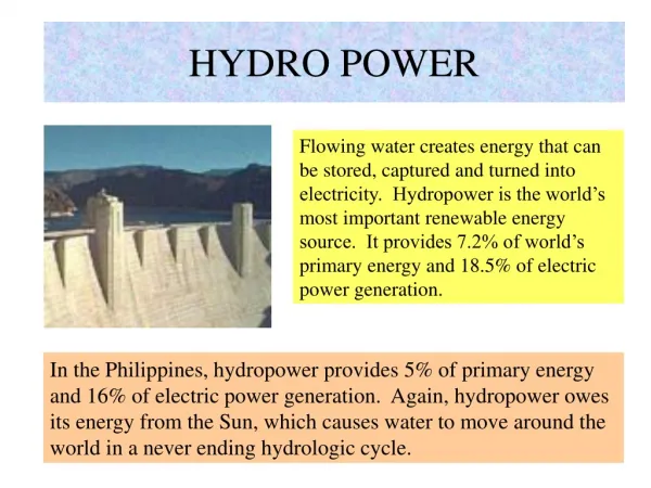
In hydroelectric power plant, the water energy is utilized to drive the turbine which, in turn, runs the generator to produce electricity. During the water is in the dam and flows through the penstock and spread out of the nozzle, it has three types of energy, they are potential, kinetic and pressure energy.
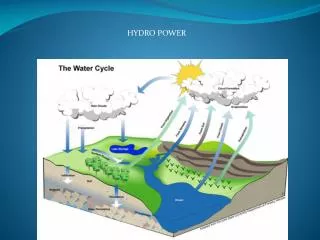
Power From a Micro-Hydro Plant The energy in a hydroelectric system starts out as potential energy by virtue of its height above some reference level—in this case, the height above the powerhouse. Water under pressure in the penstock is able to do work when released, so there is energy associated with that pressure as well. Finally, as water flows there is the kinetic energy that is associated with any mass that is moving. Figure below suggests the transformations between these forms of energy as water flows from the forebay, through the penstock, and out of a nozzle. 3
It is convenient to express each of these three forms of energy on a per unit of weight basis, in which case energy is referred to as head and has dimensions of length, with units such as “feet of head” or “meters of head.” The total energy is the sum of the potential, pressure, and kinetic head and is given by where z is the elevation above a reference height (m) or (ft), p is the pressure (N/m2) or (lb/ft2), γ is the specific weight (N/m3) or (lb/ft3), v is the average velocity (m/s) or (ft/s), and g is gravitational acceleration (9.81 m/s2) or (32.2 ft/s2). 4
Potential of River Water as Small Hydro Power Plant To obtain the potential of river water as small hydro power plant, a survey should be done. It is consists of; 1. Social and economical survey 2. Electrical and mechanical survey 3. Civil survey
Potential of River Water as Small Hydro Power Plant Social and economical survey
Potential of River Water as Small Hydro Power Plant Electrical and mechanical survey Two important components related to the electrical and mechanical survey are water flow, Q and head, H.
Potential of River Water as Small Hydro Power Plant Water flow measurement method
Potential of River Water as Small Hydro Power Plant Water flow measurement using bucket method
Potential of River Water as Small Hydro Power Plant Water flow measurement using float method
Potential of River Water as Small Hydro Power Plant Water flow measurement using current meter method
Potential of River Water as Small Hydro Power Plant Head measurement method Head is the different in height between the water level of the planed forebay and the planed position of the turbine shaft. There are three methods to measure the head, H 1. Leveling method 2. Water level method 3. Theodolite
Potential of River Water as Small Hydro Power Plant Head measurement using leveling method The head, H is given by H=h1+h2+h3+…+hn
Potential of River Water as Small Hydro Power Plant Head measurement using water level method
Potential of River Water as Small Hydro Power Plant Head measurement using theodolite A theodolite can measure distance, Height and angle, data are recorded Manually.
Pipe Losses Figure below shows the friction loss, expressed as feet of head per 100 feet of pipe, for PVC and for polyethylene (poly) pipe of various diameters. PVC pipe has lower friction losses and it is also less expensive than poly pipe, but small diameter poly may be easier to install since it is somewhat flexible and can be purchased in rolls from 100 to 300 feet long. 17
It can be written that the energy delivered by a micro-hydro system is given by where e is the efficiency of the turbine/generator. From eq. above comes the following very handy rules-of-thumb for ≈50%-efficient turbine/generator systems (which is in the right ballpark for a micro-hydro plant): 18
Example 1. Power from a Small Source. Suppose 150 gpm of water is taken from a creek and delivered through 1000 ft of 3-in.-diameter polyethylene pipe to a turbine 100 ft lower than the source. Use the rule-of-thumb to estimate the power delivered by the turbine/generator. In a 30-day month, how much electric energy would be generated? 20
Solution 1. 21
A river has water flow, and head, . Design of micro hydro power plant consists of: a. Choice of turbine b. Choice of generator c. Grounding system d. Protection system e. Size of cable Figure: Layout of micro hydro power plant
a. Choice of turbine Table: standart turbine Figure : Reaction turbine Figure: impulse (Pelton)
Types of turbine: • Impulse turbines capture the kinetic energy of high-speed jets of water squirting onto buckets along the circumference of a wheel. • Reaction turbine plays only a modest role, and instead it is mostly the pressure difference across the runners, or blades, of these turbines that creates the desired torque. • Pelton wheel, water squirts out of nozzles onto sets of twin buckets attached to the rotating wheel. 24
Pelton turbine Determination of the flow velocity. 25
From flow velocity v and flow rate Q we can determine an appropriate diameter for the water jets. For nozzles with needle valves, the jet diameter is on the order of 10–20% smaller than the nozzle, but for simple, home-scale systems, the jet and nozzle diameters are nearly equal. Using Q = vA along with eq. above we can determine the jet diameter d for a turbine with n nozzles: Solving for jet diameter gives 26
Example 2: Nozzles for a Pelton Turbine. A penstock provides 150 gpm (0.334 cfs) with 50 ft of head to a Pelton turbine with 4 nozzles. Assuming jet and nozzle diameters are the same, pick a nozzle diameter. Solution 2: 27