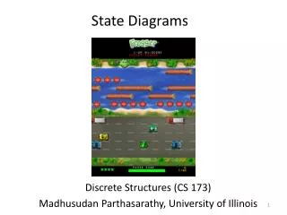
State Diagrams
State Diagrams. CSC 422 Kutztown University Dr. Spiegel. State or Statechart Diagrams. Finite state machine for 1 class show states objects in class can be in show responses to external stimuli States have associated code can have internal finite state machines Transitions


State Diagrams
E N D
Presentation Transcript
State Diagrams CSC 422 Kutztown University Dr. Spiegel
State or Statechart Diagrams • Finite state machine for 1 class • show states objects in class can be in • show responses to external stimuli • States • have associated code • can have internal finite state machines • Transitions • show when state changes
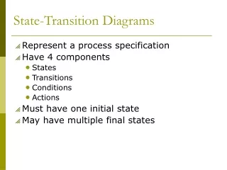
State Diagrams • State diagrams are used to show possible states a single object can get into • shows states of an object • How object changes state in response to events • shows transitions between states • UML state diagrams are a variation of Statecharts • Statecharts are hierarchical state machines • Statecharts have formal semantics
State Diagrams: States • States are represented as rounded boxes which contain: • the state name • and the following optional fields • entry andexit actions: entry and exit actions are executed whenever the state is entered or exited, respectively • internal transitions: internal transitions do not activate the entry and exit actions (different than self-transitions which activate the entry and exit actions). • activities: Typically, once the system enters a state it sits idle until an event triggers a transition. Activities help you to model situations where while in a state, the object does some work that will continue until it is interrupted by an event • deferred events: If an event does not trigger a transition in a state, it is lost. In situations where you want to save an event until it triggers a transition, use deferred events
State Diagrams: States Tracking entry action entry / setMode(on Track) exit / setMode(off Track) newTarget / tracker.Acquire() do / followTarget selfTest / defer exit action internal transition activity deferred event Note that, “entry”, “exit”, “do”, and “defer” are keywords
State Diagrams: Transitions • Transitions • source state and target state: shown by the arrow representing the transition • trigger event: the event that makes the transition fire • guard condition: a boolean expression that is evaluated when the trigger event occurs, the transition can fire only if the guard condition evaluates to true • action: an executable atomic computation that can directly act on the object that owns the state machine or indirectly on other objects that are visible to the object • initial and final states: shown as filled circle and a filled circle surrounded by an unfilled circle, respectively source state target state trigger-event[guard-condition]/action
State Diagrams shows the initial (default) state / getFirstItem getNextItem [not all items checked] Checking do / checkItem cancelled shows the final state
Initial State /getFirstItem Checking do: checkItem Dispatching do: delivery Delivered Waiting State Diagram Example: Order Object [stillMore] / getNextItem [AllItemsChecked && AllItemsAvailable ] [AllItemsCheck && SomeNotAvailable ] Delivered ItemReceived [AllItemsAvailable] ItemReceived [SomeNotAvailable]
Initial State /getFirstItem Checking do: checkItem Dispatching do: delivery Delivered Waiting Cancelled Example with Cancelled State [stillMore] / getNextItem [AllItemsChecked && AllItemsAvailable ] ItemReceived [AllItemsAvailable] [AllItemsCheck && SomeNotAvailable ] Delivered Cancel Cancel Cancel ItemReceived [SomeNotAvailable]
Active Dispatching do: delivery Checking do: checkItem Waiting Delivered Cancelled Example: Add Super State /getFirstItem [stillMore] / getNextItem [AllItemsChecked && AllItemsAvailable ] [AllItemsCheck && SomeNotAvailable ] ItemReceived [AllItemsAvailable] Delivered ItemReceived [SomeNotAvailable] Cancel
Rejected Authorizing do: checkPmt Authorized Delivered Concurrent State Diagrams • Order object of example also has states associated with the payment authorization • Could Authorize betweenDispatching andDelivery. Not nice. • Concurrency better • system in 2 stateswhile in concurrentmode [Payment not OK] [Payment OK] deliver
Waiting Cancelled Checking Dispatching Delivered Authorizing Authorized Rejected Concurrency ExampleOrder Object cancel delivered end
Concurrency Example (cont) • Inside the concurrency block the Order object is in 2 states; when it leaves it is only in one • Order object starts out in both the Checking and Authorizing states • If the Authorizing:checkPmt step finishes first • if successful, state is Authorized and Checking • else exit concurrent phase to Rejected • else could be Authorizing/Waiting or Authorizing/Dispatching and so on.