Download
1 / 30
1.23k likes | 2.43k Vues
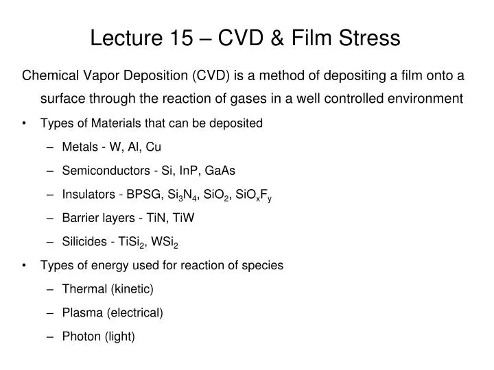
Lecture 15 – CVD & Film Stress. Chemical Vapor Deposition (CVD) is a method of depositing a film onto a surface through the reaction of gases in a well controlled environment Types of Materials that can be deposited Metals - W, Al, Cu Semiconductors - Si, InP, GaAs

E N D
Lecture 15 – CVD & Film Stress Chemical Vapor Deposition (CVD) is a method of depositing a film onto a surface through the reaction of gases in a well controlled environment • Types of Materials that can be deposited • Metals - W, Al, Cu • Semiconductors - Si, InP, GaAs • Insulators - BPSG, Si3N4, SiO2, SiOxFy • Barrier layers - TiN, TiW • Silicides - TiSi2, WSi2 • Types of energy used for reaction of species • Thermal (kinetic) • Plasma (electrical) • Photon (light)
CVD can be further defined by the pressure range and type of energy used for the reactive species CVD (thermal)-most widely used Atmospheric pressure (APCVD) Low pressure (LPCVD) <75 mT Very low pressure (VLPCVD) <10 mT CVD (plasma) Plasma enhanced (PECVD) CVD (photon) Photon induced (PH-CVD) Laser assisted (LCVD) Types of CVD
Reaction Mechanisms • Mass transport of the reactant in the bulk • Gas-phase reactions (homogeneous) • Mass transport to the surface • Adsorption on the surface • Surface reactions (heterogeneous) • Surface migration • Incorporation of film constituents, island formation • Desorption of by-products • Mass transport of by-products in bulk 1 9 2 8 3 5 6 7 4
Reaction Mechanisms cont. 1/2 Laminar flow (U) d(x) L dx uL Re = ____ 2L 3Re = ____ x u (x) = ____ C 2L F =D ___ 3Re The boundary layer thickness, d(x),is a function of distance along the substrate x By integrating the boundary layer thickness over the length, L, of the plate, substituting the Reynolds number equation, and using the value of d for dx in Fick’s law, we get: = gas viscosity = gas density u = gas stream velocity parallel to the substrate The film growth rate in the mass flow controlled regime should depend on the square root of the gas velocity, u. At high flow rates, the growth rate reaches a maximum and then becomes independent of flow
Reaction Mechanisms, cont. C 2L F =D ___ 3Re • At low flow rates, the film growth rate shows a square root dependence. • At high flow rates, the growth rate reaches a maximum and becomes independent of flow. • At these high flow rates, the reaction rate controls the deposition (i.e. ) The rate limiting processes can dictate how wafers are stacked in the CVD chamber. Surface reaction is rate limiting Mass transport is rate limiting
Film Growth Mechanisms What happens once the reactants reach the surface and the film grows? • Nucleation of growth • Generally a stochastic process that strongly depends on surface propagation, temperature, gas phase reactions. • Type of growth • Island vs layer determines grain size and boundaries while step vs cluster determines roughness and grain orientation • Material bonding • Chemical bonds vs adhesive via coordination bonds (van der walls, hydrogen, ionic) which determines if layer can exist and not delaminate • Stresses within the film • Residual stresses arise due to lattice mismatch and thermal expansion mismatch (CTE) which is strongly dependent on the temperature of deposition, growth mechanism, and deposition method
Film Growth Mechanisms cont. • Material structure • Polycrystalline, amorphous, epitaxial, columnar - the type affects everything from residual stresses to roughness as well as mechanical, thermal, and electrical properties • Uniformity of film • In terms of thickness, composition, structure, and properties which are strongly affected by numerous factors including temperature, pressure, process type (CVD, PECVD, PVD), chamber geometry, flow type and dynamics, reaction type, mobility of species on surfaces… • Mobility of species on the surface • Depends on many factors including substrate energy, vapor energy, reaction energies, temperature, activation energy, charge trapping, surface roughness • Motion of the atoms on the surface is the key to most all growth mechanisms i.e. surface mobilities are important to understand
Step Coverage 0 q=180 q is angle of arrival 0 q=90 0 q=270 • CVD processes are useful in coating micromachined features. • Coatings can be used to passivate or isolate underlying surfaces. • A denotes a uniform and ideal coating • B denotes a MFP that allows coating of the surface but not rearrangement due to migration • C shows a MFP that is too short to allow coating of the bottom features and little rearrangement due to migration.
APCVD Not as common as other CVD processes • Common application • Epitaxial semiconductor films (Si, GaAs, InP, HgCdTe) • Doped and undoped low temp oxides • Typical process conditions • Atmospheric to slightly reduced pressure (760-76 Torr) • Relatively low temperatures (300-500 oC) • Reactor walls cooled to minimize particulate and impurity problems from walls • Mass transport limited
LPCVD • Common application • Doped and undoped high temperature SiO2 • Silicon nitride, PolySi • Tungsten, Tungsten silicide • Typical process conditions • 75 Torr or less (mtorr range not uncommon) • 300-900 oC • Surface reaction rate limited • Most commonly hot wall furnace, other reactor setups include single wafer showerhead, single wafer rotating disk, horizontal multiwafer epi reactor
PECVD • Common application • Low temperature insulators over metals • Typical process conditions • mtorr to 5 torr • 100-350 oC • Surface reaction rate limited • Most commonly hot wall furnace
Stresses in Thin Films Stresses can be: Intrinsic – caused during film growth • Growth of film • Lattice mismatching or impurities • Phase transformation – plastic deformation • Impurity or gas incorporation Extrinsic-caused by external forces • Temperature • Caused by different materials or same material with temperature gradient • Packaged induced stresses Intrinsic stresses are often largest
Stresses in Thin Films Intrinsic stress • Initial film growth can lead to compressive stress as the film expands parallel to the surface • Thick films can cause buckling, blistering, or delamination • Thin films may be in tensile stress where the film contracts • Films can crack if high enough to reach the fracture limit • Annealing can help to decrease both tensile or compressive stresses • Intrinsic stresses can also affect film properties like electrical characteristics through defect formation
E E ____ x,y = ____ x,y 1 - 1 - Stress Calculations The total stress in a thin film: total = ext + thermal + int where • ext = external applied stress (e.g. N2 pressure to membrane) • thermal = from heating or cooling sample (e.g. resistive heating of sample) • int = intrinsic stress due to film formation (e.g. sputtering process) We can assume no stress occurs normal to the surface, and film materials are isotropic, thus Where • E = Young’s modulus, or modulus of elasticity, or sometimes just modulus • = Poisson’s ratio (must be -1 < < 0.5, but for most materials 0 < < 0.5) • = biaxial modulus (used for most thin films) -independent of orientation
Poisson’s Ratio 0.0 - Cork, Beryllium 0.20 - Pyrex, quartz 0.22 - Borosilicate glass, soda lime glass, silicon 0.25-0.35 - Most metals 0.40 - Silicone, polyimide, polycarbonate, acrylic 0.50 - Rubber (incompressible) Some materials, mostly polymer foams, have a negative Poisson’s ratio; if these auxetic materials are stretched in one direction, they become thicker in perpendicular directions *http://www.product-technik.co.uk/News/news.htm
Intrinsic Stress Contributions Intrinsic stress • Doping (int > 0 or int < 0) • Type of dopant affects stress i.e. boron is small (tensile) compared to silicon while phosphorous is large (compressive) compared to silicon • Atomic peening (int < 0) • Ion bombardment by sputtered atoms densifies thin films making them more compressive i.e. magnetron sputtered films • Microvoids (int > 0) • May form from by products during deposition that escape as gases but the gaps left behind are not filled • Gas entrapment (int < 0) • Gases like hydrogen trapped in a nitride film can make the film compressive but annealing could render it tensile
Intrinsic Stress Contributions cont. Intrinsic stress (cont) • Shrinkage (int > 0) • Polymers undergo shrinkage during cure may lead to severe tensile stress, difficult to measure mechanical properties due to the time dependent mechanical response. • Grain boundaries (int ?) • Grain boundaries play a role in the intrinsic stress of the film but the relationship of the grain structure and inter-atomic spacing to the intrinsic stress is material dependent and not well understood
Trends with Metal Thin Films Stresses • Stresses are mostly between 108 and 1010 dyn/cm2 (highly stressed), and are: • Refractory metals - higher stress: Mo, Ta, Nb, W Ta • Soft metals - lower stress: Cu, Ag, Au, Al • Metals that have high diffusion rates on surfaces (i.e. Al) generally deposit with • Metals (i.e. W) with low diffusion rates (typical of sputtering) accumulate
Trends with Dielectric Thin Film Stresses Most dielectric films • Stresses are often slightly in magnitude than metals and are Oxide films • Stresses are often due to water absorption but can be annealed and become Silicon nitride films • Stresses are mostly by CVD deposition (due to hydrogen incorporation) but if annealed can become highly Plasma deposited films • As RF is increased, the film generally becomes more
Stresses in Thin Films Thermal stresses • A thin film at deposition temperatures is strain free, as the film cools, the difference in thermal expansion ( ) between the film and the substrate it was deposited on induces a strain th = (f - s)(Td - Tr) • The sign of the difference in thermal expansion determines compressive () or tensile () stress (assume deposition temp is greater than room temp)
Stress Calculation – Example 1 Polyimide films have CTEs ranging from 3-50 ppm/ºC and borosilicate glass (coverglass) have CTEs that range from 1 to 9 ppm/ºC. 1400 series PI has a CTE of 50 ppm/ºC, and a cure temperature of 350ºC. Corning 0211 coverglass (most common type) has a CTE of 7.4 ppm/ºC. After curing 60 min at 350ºC we can assume the film and coverglass are in equilibrium and “stress free”. Upon cooling to 20ºC results in a linear uniaxial contraction of the PI: Thus for a 25 mm square area (if the layers weren’t attached) the PI would be (16.5-2.4)*25 = 0.352mm smaller per side than the coverglass. Note: Assume the carrier is always much thicker than the film, thus the CTE mismatch will be entirely absorbed by the film (e.g. wafers are 400-500 µm thick and #2 coverglass is 190-230 µm thick, while most films are < 10 µm thick) Thus for example 1, the film would be in “tensile” stress (not compressive) In general, films stress can be 0 – 1011 dyn/cm2 and can be either tensile or compressive.
E x,y = ____ x,y 1 - Stress Calculation – Example 2 Calculate the stress for PI cured at 3500C on 0211 coverglass (PI has a modulus of 3GPa, Note: 1 Pa = 1 N/m2 = 10 dyn/cm2) Equation used to calculate thermal stress in an isotropic thin film: Thus
Stress Calculation – Example 3 Determine the intrinsic stress of deposition of NiCr on Si if the stress measured at room temperature after deposition is 6x10⁹ dyn/cm2. (Note: ν = 0.27, E = 200 GPa, and CTE = 10-5/ºC for NiCr, CTE = 2.6 x 10⁻⁶/ºC for Si, assume a deposition temperature of 80ºC and room temperature is 20ºC) total = thermal + int Note: for metal deposition, most of the stress is because of the deposition process (internal stress) and not due to material CTE mismatch
Stress Calculation – Example 4 If we wanted stress free NiCr at room temperature, what deposition temperature should we use (assume intrinsic stress doesn’t change with respect to temperature)? total = thermal + int Where
CTE Mismatch of Some Glasses to Silicon Silicon to Pyrex (Corning 7740 has been the closest match to Si) Silicon to BSG and SD-2
Wafer Bow Using the Stoney Equation to relate uniaxial force per length (film stress) to substrate radius of curvature: Where, R - radius of curvature of the bent substrate Ysubstrate – biaxial modulus of substrate = Thus,
Wafer Bow – Assumptions & Example Assumptions: • film thickness uniform and << substrate • film and substrate have isotropic elastic properties • without film substrate has no bow • stress is homogeneous and equi-biaxial • substrate and film are roughly circular Example: Calculate the wafer bow for a 0.1 µm thick deposition of NiCr on a 400 µm thick Si wafer (for silicon, assume a Young’s modulus of 130 GPa). Thus, If we wanted a radius of curvature of only 10 meter what would we need to do? Increase the thickness by 7.41 times – 0.741 µm thick deposition of NiCr.
Quotes • Maturity is the ability to do a job whether or not you are supervised, to carry money without spending it, and to bear an injustice without wanting to get even. -Ann Landers • Winners have simply formed the habit of doing things losers don't like to do.- Albert Gray • People are like stained glass windows: they sparkle and shine when the sun's out, but when the darkness sets in, their true beauty is revealed only if there is light within. - Elizabeth Kubler-Ross • Forgiveness is a gift you give yourself.