Download
1 / 66
660 likes | 944 Vues
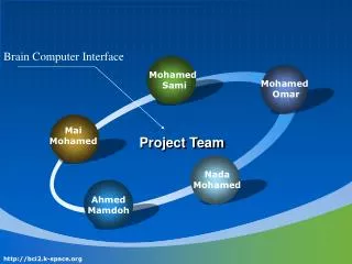
Brain Computer Interface. Mohamed Sami. Mohamed Omar. Mai Mohamed. Project Team. Nada Mohamed. Ahmed Mamdoh. http://bci2.k-space.org. B rain C omputer I nterface BCI. Supervisors Prof.Dr Abu Bakr M. Youssef Assistant Prof.Dr Yasser M.Kadah. http://bci2.k-space.org.

E N D
Brain Computer Interface Mohamed Sami Mohamed Omar Mai Mohamed Project Team Nada Mohamed Ahmed Mamdoh http://bci2.k-space.org
Brain Computer InterfaceBCI • SupervisorsProf.Dr Abu Bakr M. YoussefAssistant Prof.Dr Yasser M.Kadah http://bci2.k-space.org
Motivation for BCI Research • There are , more than 200,000 patients live with the motor sequelae of serious injury. Locked-in Syndrome • Neurological diseases may lead to paralysis of the entire motor system . • Unable touse their muscles and therefore cannot communicate their needs, wishes, and emotions. http://bci2.k-space.org
Reason of BCI • Allow a user to communicate with a computer through his Brain • The user can think and the computer recognizes what he thought about. • This is what we call a Brain-Computer Interface (BCI) [or Brain-Machine Interface (BMI)]. http://bci2.k-space.org
The Dream • People always think about controlling environments from their mind • Anyone wish if he could read the people thoughts and know what they are thinking of him • Some people want to store their dreams and record it while they sleeping http://bci2.k-space.org
Dream vs. Reality • Dream BCI • Think to whatever you want • Without recognition errors • Whenever you want • Physiological problems • No thought sensor • Partial brain knowledge • Noisy signals • Solutions in the BCI community (reality) • Limited thought • Limited recognition accuracy http://bci2.k-space.org
BCI community About 60 research groups About 300 researchers Increasing published papers http://bci2.k-space.org
Our Goals 1. Recording Brain Signal Using EEG electrodes. 2. Isolation between subject and electronic circuit 3. Designing Data Acquisition System 4. Signal Selection 5. Interfacing with Computer by Soundcard 6. Implementing real time analysis Classification data
BCI Categories • Invasive and Non-Invasive BCIs • Online and Offline BCIs • Imaginary and Mental Tasks http://bci2.k-space.org
3. Online Feedback 1. Data Acquisition 2. BCI System General scheme High level commands Feedback Control interface Application Mental state Electrical activity Pre-processing Feature extraction Classification Bio-sensor The brain On the computer http://bci2.k-space.org
Nervous System Motor Brain CNS Spinal Cord Nervous System Cranial Nerves PNS Sensory Spinal Nerves http://bci2.k-space.org
Human Brain http://bci2.k-space.org
EEG • Electroencephalography or EEG is the measurement of neural activity within the brain. • EEG has been used to detectlow oxygen and high carbondioxide levels. • A clinical use of EEG is in the diagnosis of epilepsy. http://bci2.k-space.org
EEG Signal http://bci2.k-space.org
EEG Lead System http://bci2.k-space.org
Data Acquisition http://bci2.k-space.org
Overview Electrode Isolation Pre Amplifier Electrode Isolation Pre Amplifier Electrode Isolation Pre Amplifier Gain Amplifier Matlab Workspace LPF MUX Sound Card Electrode Isolation Pre Amplifier Latch Electrode Isolation Pre Amplifier Parallel Port Electrode Isolation Pre Amplifier http://bci2.k-space.org
Biopotential Sensors • Electrodes are Biopotential sensor. • There are different types of electrodes: • Gold electrode. • Silver electrode. http://bci2.k-space.org
Isolation • Medical procedures usually expose the patient to more hazard than at home or workplace. • Our main goal is to break ground loop . • We decide to do that by low cast and effective way by using: • Isolation transformer as power isolation. • Opto-Couplers as signal isolation. http://bci2.k-space.org
Continue Isolation • In our design we used the PC817 due to: • Its low turn-on and off time and high. • Isolation voltage between input. http://bci2.k-space.org
Instrumentation Amplifier • Amplifying differential input • There are two stage of signal amplification: • Pre-Amplification • Gain-Amplification • We used AD620according to many better features on it: • Lower cost • High accuracy • Low noise • High Gain Ability http://bci2.k-space.org
AD620 Schematic http://bci2.k-space.org
Signal Selection Multiplexer: Select data from two or moredata sourcesinto a single channel. • There are two types of multiplexers: • Analog Multiplexer. • Digital Multiplexer. • we used Analog Multiplexer and we choose M54HC4051 IC • Some features of M54HC4051: • Low power dissipation • Fast switching • High noise immunity • Wide analog input voltage range http://bci2.k-space.org
M54HC4051 Schematic http://bci2.k-space.org
Latch • Changeoutput state only in response to data input • Transfer data from parallel port to MUX and holding it using LE (latch enable). • In our design SN74LS373 As latch IC. http://bci2.k-space.org
SN74LS373 Schematic http://bci2.k-space.org
Signal Filtering • A low-pass filter is a Filter that passes low frequensyComponent well, reduces frequencies higher than the cutoff frequency. • It is sometimes called a high-cut filter, or treble cut filter. • We use active 2nd order low pass filter we used UA741 IC.
LPF Schematic http://bci2.k-space.org
Parallel Port The Parallel Port is the most commonly used port forinterfacing home made projects • Hardware Properties • 8 output pins accessed via the DATA Port • 5 input pins (one inverted) accessed via the STATUS Port • 4 output pins (three inverted) accessed via the CONTROL Port • The remaining 8 pins aregrounded • Why Parallel Port ? • EasyImplementation and Installation • Allow FullSoftware Control without- need any Counters & • Clock to Switch between Channels Ability of Communication with Matlab http://bci2.k-space.org
Sound Card A sound card is a Computer PCI Card that can input and outputSoundunder control of computer programs General characteristics 1-Sound Chip 2- multi-channel Dacs & A/D 3-ROM or Flash memory http://bci2.k-space.org
Continue Sound CardInternal Block
Why we choose Sound Card • Fixed and Low Cost Acquisition Card • Easy in Implementation and installation • Ability to Convert from Analog to Digital with very high accuracy and vise versa • Easy Communication with Matlab • Ability to detectlow Frequencies • Sampling Data in wide rang (8000 to 44100) • Better than designing new Interfacing System and this System in Situation to not work because of hardwaretroubleshooting http://bci2.k-space.org
Acquiring Data with a Sound Card http://bci2.k-space.org
Data Acquisition Programs 4th Release 1st Release 2nd Release 3rd Release Each Channel Online Plotting Online Signal with Filtering Drawing With Selection Online Classifier http://bci2.k-space.org
1st Release http://bci2.k-space.org
2nd Release http://bci2.k-space.org
3rd Release http://bci2.k-space.org
4th Release imagination of right hand movement imagination of left hand movement http://bci2.k-space.org
Analytic methods The process of EEG signal analysis and classification consists of the Following three steps: Signal preprocessing Feature extraction Statistical classification http://bci2.k-space.org
Eye blink Power line Subject Electrode contact Heart rate Signal Preprocessing Noisy signal • Power line 50/60 Hz • Electrode contact • Eye movements • Other movements ? Background brain activity Experiment protocol Physiologic noise Environmental noise Mental task Measured signal
Start Offline Type of work Online classification Work on exist dataset Record our dataset Record EEG signal Read dataset Feature extraction feature extraction Feature extraction Make hypothesis test hypothesis test Classification Decision F Visual O/P Feature available Test next feature T Classification Red Green Test classifier http://bci2.k-space.org
Offline DatasetBCI Competition 2003Data Set Ia: ‹self-regulation of SCPs› provided by University of Tuebingen,Germany, Dept. of Computer Engineering (Prof. Rosenstiel) Datasets were taken from a healthy subject he was asked to move a cursorup and down on a computer screen. Data • 6 EEG electrodes are used referenced to the vertex electrode Cz • Channel 1: A1-Cz (A1 = left mastoid) • Channel 2: A2-Cz (right mastoid) • Channel 3: 2 cm frontal of C3 • Channel 4: 2 cm parietal of C3 • Channel 5: 2 cm frontal of C4 • Channel 6: 2 cm parietal of C4 • Sampling rate of 256 Hz. Trial structure overview consisted of three phases 1-s rest phase,1.5-s cue presentation phase and 3.5-s feedback phase. http://bci2.k-space.org
Continue Offline Dataset During every trial, the task was visually presented by a highlighted goal at the top or bottom of the screen to indicate negativity or positively from second 0.5 until the end of the trial. The visual feedback was presented from second 2 to second 5.5. Only this 3.5 second interval of every trial is provided for training and testing. • Trails separated into training set (268 trials) which is 2-D Matrices 135x5377 and 133x5377 testing set The test set (293 trials). Every line of a matrix contains the data of one trial. The first column codes the class of the trial (0/1). • Note For our implementation we constructed the test set from the train set. That was done by selecting 100 trails from class 0 and 100 trails from class 1. http://bci2.k-space.org
Continue Offline Dataset Approach • We used MATLAB (release 13) for analysis. • We separated the channels of each class to be 135x896 matrix for channels in class 0 and 133x896 matrix for class 1 channels. • For each EEG channel, we plotted the time-domain and frequency-domain averages across trials for each class. Note • In our online BCI approach, we constructed our own dataset which consist of training set & testing set. • The training set was used to tune the parameters of the classification algorithm. • We also applied all the pre-processing techniques as in the offline work. http://bci2.k-space.org
Feature Extraction Steps of feature extraction • Choosing feature • Features Vector Form http://bci2.k-space.org
Choosing Features Time Domain Features • mean • Variance http://bci2.k-space.org
Continue Frequency domain features Short-Time Fourier Transform • First we transform all signals to frequency domain by (FFT). • Then we get mean & variance in frequency domain . • calculate the amplitudes at 20 Hz. Welch method Estimate the power spectral density (PSD) of a signal using Welch is done using Pwelch Matlab function
Form features vector Signal 1 Signal2 Signal3 Signal4 : : : : : : : Channel 1 feature vector Std1 Std2 Std3 Std4 : : : : : : : : : Class 0 Class 0 Class 1 Class 1 http://bci2.k-space.org