Download
1 / 58
580 likes | 736 Vues
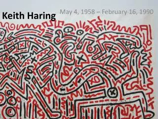
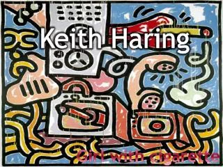
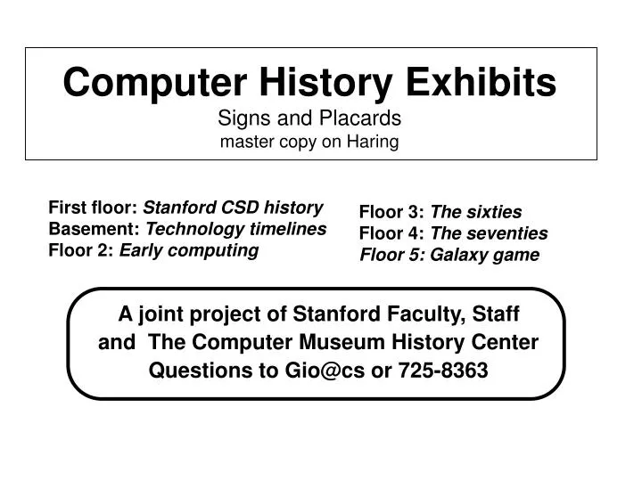
A joint project of Stanford Faculty, Staff and The Computer Museum History Center Questions to Gio@cs or 725-8363. Computer History Exhibits Signs and Placards master copy on Haring. First floor: Stanford CSD history Basement: Technology timelines Floor 2: Early computing.

E N D
A joint project of Stanford Faculty, Staff and The Computer Museum History Center Questions to Gio@cs or 725-8363 Computer History Exhibits Signs and Placards master copy on Haring First floor: Stanford CSD history Basement: Technology timelines Floor 2: Early computing Floor 3: The sixties Floor 4: The seventies Floor 5: Galaxy game
case 11 Computer History Exhibits case f 2 case f 1 case2 case3 case1 case4 case5 Basement: Timelines First floor: Early Stanford CSD history 2nd: 50’s:Univac & Whirlwind 3rd: 60’s: IBM 360 & DEC PDP-6 4th: 70’s: Aple II & Cray Fifth floor: Galaxy game A joint project of . Stanford Faculty, Staff, & The Computer Museum History Center Questions to Gio@cs or look at http://www-cs.stanford.edu (museum)
Computer History Exhibits Opening Talks in room B1, Nov. 5th, 5:30 pm Donald Knuth: George Forsythe and the Development of Computer Science Gordon Bell: Values & Issues in Preserving Historical Computer Artifacts Serra street Exit to outside B1 Entrance to Basement Lecture Hall First floor Basement Campus Drive
display case 1 Computer History Exhibits Installation in Progress Watch this Space Computer History Exhibits Installation in Progress Watch this Space display case 1
Dark areas are due to a head crash in 1969. Platter from General Precision Librascope L 4800 head-per-track Disk Unit Stanford AI Lab DEC PDP-6, November 1967 Storage capacity per side ca. 1,120,665 words of 36 bits Capacity per unit (10 inner sides of 6 platters) 11,206,650 words or ca. 48 M bytes. Total 5484 heads (and tracks). Total weight 5200 lbs Rotational speed 900 rpm, Avg. access time 35 msec. Transfer rate 1.6 m sec/word or 2.7 M byte/sec Startup current 300 amps, Startup time 5 minutes, thermal stabilization 2 hours Cost $300,000 ($1,420,000 today) The photograph shows the unit with the disks and the electronics bay (2000 lbs) removed. Courtesy of Martin Frost
Storage capacity per side ~1,120,665 words of 36 bits Capacity per unit (10 inner sides of 6 platters) 11,206,650 words or ~48 M bytes. Total 5484 heads (and tracks) Rotational speed 900 rpm Avg. access time 35 msec. Transfer rate 1.6 m sec/word or 2.7 M byte/sec Startup current 300 amps Startup time 5 minutes, thermal stabilization 2 hours Weight 5200 lbs Cost $300,000 ($1,420,000 today) Platter from General Precision Librascope L 4800 head-per-track Disk Unit Stanford AI Lab DEC PDP-6 November 1967 Courtesy of Martin Frost Dark areas are due to a head crash in 1969. Total Tracks (and Write-Read heads): 5484 (includes 300 spares) Bits/Track: 80,256 Bits/Sector: 66 Sectors/Rev: 1216 based on CPI 1997 159.1 159.6 160.0 160.2 160.1 160.3 160.5 1967 32.9 32.9 33.0 33.1 33.2 33.3 33.4 33.5 33.6 33.7 33.8 33.9 33.4
Apple Macintosh Hard disk unit ca. 1989 5 platters, 10 sides one head per side Capacity 20 Megabytes Courtesy of SUMEX SONY Corporation 3.5” Floppy disk drive ca. 1991 High density, double sided one head per side Capacity/floppy 1.4 Megabytes With disk in protective, low friction carrier. Courtesy of SUMEX 8” Floppy disk first use ca. 1965 Single sided disk Capacity/floppy ca. 150 Kilobytes Courtesy of Vaugn Pratt
Apple Macintosh Hard disk unit ca. 1989 5 platters, 10 sides one head per side Capacity 20 Megabytes Courtesy of SUMEX 8” Floppy disk first use ca. 1965 Single sided disk Capacity/floppy ca. 150 Kilobytes Courtesy of SONY Corporation 3.5” Floppy disk drive ca. 1991 High density, double sided one head per side Capacity/floppy 1.4 Megabytes With disk in protective, low friction carrier. Courtesy of SUMEX 5” Floppy disk drive Shugart Corporation first use ca. 1977 Single sided disk Capacity/floppy 360 Kilobytes Courtesy of Vaugn Pratt
Digital Equipment Corporation Model 846 single platter disk cartridge from SUMEX DEC PDP-11, ca. 1972. Cut open to show disk The 2 reading heads were mounted on slides in the drive and entered the unit through the small port in the rear. Larger units were composed of multiple, up to 11, platters Storage capacity per side, using 200 formatted tracks, ca.1.1 Megabytes of 8 bits Capacity per unit 2.2 Megabytes. Rotational speed 2400 rpm. Average seek time for head movement 60 msec. Rotational latency 12.5 msec. Transfer rate 0.312 Megabyte/sec. Courtesy of Tom Rindfleisch, SUMEX
display case 2 Computer History Exhibits Installation in Progress Watch this Space Computer History Exhibits Installation in Progress Watch this Space display case 2
Lightning Calculator, ca. 1930. The Lightning Adding Machine Company, Los Angeles CA This calculator belonged to Prof. George Forsythe. This American calculator copies the design of the Pascaline, first designed by Blaise Pascal in 1642. The pen is used to add or subtract digits in any of 8 decimal conditions by rotating one of the disks. A lug on each wheel creates a carry when the 9 digit is passed. This improved version had a single lever to reset all digits to zero. Courtesy of the Estate of George and Sandra Forsythe and The Computer Museum.
George Elmer Forsythe Founding Chairman of the Stanford Computer Science Department 1965-1972 born 1917 in State College, PA graduated from Swarthmore College 1937 PhD in Mathematics from Brown University 1941 at Stanford University 1941-1942, 1957-1972 Air Force meteorologist 1942-1945 at UCLA’s Institute for Numerical Analysis to 1957 with John Herriot, formed the Division of Computer Science within the Mathematics department in 1961 Director of the Computation Center 1961-1965 died 1972 at Stanford, CA
George Forsythe supervised 17 PhD theses at Stanford. Many of his students became professors themselves and several became department chairs in turn. The complete tree of Forsythe’s academic descendants is available on the web pages describing these exhibits, at http://www-cs.stanford.edu, and then click on museum. courtesy of Cleve Moler and Jim Varah
Polya Hall Home of the Stanford Computer Science Department 1963- Oct.1979 Named for George Pólya (1887-1985) Prof. of Mathematics Polya: 13 Dec.1887- 7 Sep.1985 [Don Knuth]
display case 3 Computer History Exhibits Installation in Progress Watch this Space Computer History Exhibits Installation in Progress Watch this Space display case 3
IBM Card Programmed Calculator (CPC) A CPC was Stanford’s computer from 1953-1956. The tall box is the arithmetic unit, which used 1500 vacuum tubes and had 8 registers of 4 digits and 1 register of 5 digits. Digits were represented by 4 bits each, requiring 2 vacuum tubes per bit. The box on the right contained 4 mechanical accumulators of 12 digit words and 2 of of 16 digits, and 48 words of mechanical storage. Mechanical storage was implemented in the form of wheels, which were positioned by solenoids, and had contacts for readout. Instructions were read from cards, placed into the center unit, at a rate of up to 150 per minute. Through wiring a plug board placed in the arithmetic unit certain cards could be skipped, giving some control over program flow. The CPC was not yet a von Neuman machine architecture. The central unit also had a printer, which could print 120 columns of numeric output at 150 lines per minute (lpm), but only 40 columns of letters at 100 lpm. Results could also be punched on the rightmost unit, on up to 50 cards per minute. Another wiring board selected the card columns.
Wiring Plug Board, ca. 1960. IBM Corporation, NY. On pre-Von Neumann computers programs were wired. Placing the wires into plug boards allowed fast changing of programs and off-line program preparation. The wires routed the impulses obtained from cards to start and increment counter wheels, to transmit carry im-pulses to other wheels, and to set indicators for negative numbers or overflow. Printers had similar wheels, but embossed, which were rotated before striking the paper. This panel controlled a collator, a machine for merging two sets of sorted cards according to the contents of sequencing fields. The fields could be in different columns. Courtesy of The Computer Museum History Center
Data processing cards were invented by Hermann Hollerith of the U.S. Bureau of the Census. Commonly known as IBM cards they were used for data and program storage from 1890 up to the 1980’s. They had 80 columns, and up to 4 holes out of 12 positions could be punched out per column, allowing first 12, later 64, and eventually 256 distinct characters codes per column. More holes weakened them. The size of the card was based on the dollar bill of that time, so that they might be carried in standard wallets. Dollar bills are now smaller in size and in value. Silver certificate dollar bill from 1920 courtesy of Voy and Gio Wiederhold
Early Computers at Stanford Typearrived-retiredLocationspeed(+/x)Memory Prim.language msec Words/bytes IBM CPC Mar.1953-56 Elec.Lab. 760K/13M 48wired board IBM 650 Jan.1956-62? Elec.Lab. 2.2K/19K 2KW SOAP Burroughs 220 Jun.1960 Encina 200/330010KW Balgol shared with First National Bank of San Jose (overnight check processing) IBM 7090 Feb.1963?-67 Pine Hall 4.4/2532KWFORTRAN Burroughs 5500 Mar?.1963-68 Pine Hall Algol DEC PDP-1 1964 - Pine Hall ~5/18bits 64KW DEC PDP-6 Aug.1965 AI lab ~4/36bits LISP IBM/360-50 Jun.1965 SLAC 4/16 256Kb IBM/360-50 Dec.1965-7x Med.Sch. 4/16 1.128Kb PL/1 subset IBM/360-67 May 1967- Pine Hall 1.5/6 500Kb Algol W, installedas an IBM/360-65 because of an inadequate timesharing systemFORTRAN IBM/360-75 SLAC 0.75/3 1Mb FORTRAN IBM/360-91 1968 SLAC 0.2/0.4 2Mb FORTRAN DEC PDP-10 1969? -85? AI lab LISP, SAIL DEC system 2040 1976-1977 LOTS 1.0 128KW DEC system 2050 1977-19 LOTS 0.5 256KW
Early Faculty at Stanford 1953 Jack Herriot, Alan Peterson, codirectors computation center
Remington-Rand Univac Flip-Flop Assembly Model 1818A, serial 001348. Manuf’d for the U.S. Navy, Oct.1960. Courtesy of David Hermreck, Potomac, MD. Two?-bit highly reliable plug-in electro-mechanical memory unit. It uses relays, composed to form flip-flop storage cells, similar to the exposed AEC unit shown. The access time was about 1/2 sec. To avoid corrosion, all joints were soldered to be airtight, and then the unit was filled with nitrogen gas, through the valve on the side. All contacts are gold plated. Similar flip-flop units, but not sealed, were used for the IBM CPC (Card-Programmed Calculator) shown above, used at Stanford from1953 to 1956. The CPC could hold 9 words of 4 4-bit digits in vacuum tube circuits, and 48 words of 10 digits in relay storage. The CPC was hence not a von-Neumann machine architecture; programs remained external. Computation was driven by sets of cards, fed through a card reader at up to 2.5 instructions/second.
Primary Programming Languages Taught at Stanford <Tentative Draft, tell us what you know> Language years compiler machine Board wiring 1953-56 none IBM CPC Assembler 1956-60 SOAP II IBM 650 Algol 58 1960-65 Balgol Burroughs 220 FORTRAN 1963-67 FORTRAN II IBM 7090 Algol 60 1963-68 Algol Burroughs 5500 Algol W 1968-75 Wirth’s IBM/360 FORTRAN 1975 FORTRAN IV IBM/370 ALGOL 60 + 1976-77 SAIL DEC 10 PASCAL 1978-91 LOTS DEC-10 C 1991-today Apple Macintosh Java? future? Information courtesy of Claire Stager, Eric Roberts, ...
display case 3 Computer History Exhibits Installation in Progress Watch this Space Computer History Exhibits Installation in Progress Watch this Space display case 3
DEC-10 system Memory Controller Board, modified for LOTS, the Stanford Low-Overhead Time Sharing System, 1977 By 1976 semi-conductor memory prices had dropped to the extent that large number of display terminals could each have their own buffer in a timeshared system. The buffersizes were adequate for 40 lines of 80 = 3200 characters each, requiring about 320, 000 bytes for 100 terminals. This was more than provided for in the original controller design, so that boards for LOTS were modified to allow high-order addressing. On PCs and workstations today, the entire display image is buffered, omitting the need for a hardware charcter generator, but requiring up to a Megabyte per display. Courtesy of Ralph Gorin
ACME system status panel, 1966 Designed by Robert Flexer and Klaus Holtz For the time-sharing and real-time data acquisition system in The Medical school, ACME, status indicators were provided on each of the 30 terminals, to reduce user frustration. The white ACME IS ON light was pulsed periodically, so that it would decay if the system went down. YOU ARE ON signaled each time slice allocated. The WAITING FOR YOU light indicated that input was expected from the terminal or a data-acquistion port, and the SPECIAL RUN ON light warned users that a high demand data acquisition task was in progress, reducing the performance for all others. Courtesy of Gio Wiederhold
display case 4 Computer History Exhibits Installation in Progress Watch this Space Computer History Exhibits Installation in Progress Watch this Space display case 4
The SAIL language was • derived from Algol 60, • expanded with • direct access to PDP-10 I/Ofacilities, • control over external interrupts • macro-capabilities • sets and lists • data structures for associative search • multi-processing • The last three augmenta-tions were derived from LEAP, developed in 1969 by • Jerry Feldman and Paul Rovner on the Lincoln Labs TX-2. SAIL User Manual June 1973 Editor: Kurt VanLehn Stanford AI Laboratory The SAIL language was, with LISP 1.5, the primary programming language at the Stanford AI Laboratory, and used, a.o., for its research in robotics. Courtesy of Gio Wiederhold
DataDisc Display System 1971: The DataDisc (DD) used the disk you see here to store and continuously generate 32 video channels that were used as display screens on monitors around the Stanford AI Lab. 1972: The DD video channels were routed through a crossbar switch to any combination of 56 DD display terminals in the building. Users could view the same channel from multiple monitors, or multiple channels on one monitor. 1982: More and more DD channels had become very streaky and annoying, so the DD disk was replaced with RAM memory using the big 64Kbit chips in the “newDD” system designed at SAIL. Here you see the DD’s small read amplifier cards mounted around a circle. On the other side, arranged in a spiral, are the disk heads, which you can see in the shiny mirror in the back, which is the DD disk itself! (Note the dark lines on the outer portion of the disk -- from head crashes which disabled only selected channels.) One new DD memory board, holding four video channels, is to the right.
display case 5 Computer History Exhibits Installation in Progress Watch this Space Computer History Exhibits Installation in Progress Watch this Space display case 5
display case 6 Computer History Exhibits Installation in Progress Watch this Space Computer History Exhibits Installation in Progress Watch this Space display case 6
Monroe Decimal Calculator. ca. 1930 Inventor: Frank Stephen Baldwin 1839-1925. This 10-key calculator provided accurate manual computation. Its operator was called a computor. Each complete forward turn of the large crank on the right will add the value set into the 8 x 10 keys into the bottom register of the carriage. The top register counts the turns. Subtraction is achieved by turning the crank in reverse. To multiply the Repeat button is pressed and the crank turned as often as needed for the low-order digit. Then the carriage is moved to the right with the handle in front, so the next digit of the factor can be cranked in. The crank on the carriage is for resetting result and counter registers. Division is performed by subtracting the divisor left to right. Courtesy of Gio Wiederhold
Monroe Decimal Calculator,ca.1930 Inventor: Frank Stephen Baldwin 1839-1925. This 10-key calculator provided accurate manual computation. Its operator was called a computor. Each complete forward turn of the large crank on the right will add the value set into the 8 x 10 keys into the bottom register of the carriage. The top register counts the turns. Subtraction is achieved by turning the crank in reverse. To multiply the Repeat button is pressed and the crank turned as often as needed for the low-order digit. Then the carriage is moved to the right with the handle in front, so the next digit of the factor can be cranked in. The crank on the carriage is for resetting result and counter registers. Division is performed by subtracting the divisor left to right Courtesy of Gio Wiederhold
Marchant Electric Calculator, ca. 1950. Marchant Calculator Comp. , Oakland CA. This calculator was usedby Prof. George Forsythe, founding chairman of the Stanford Computer Science department. This calculator replaced the human power required in earlier machines (see the Monroe calculator) with an electric motor, a single on/off relay and a number of mechanical clutches. The key on the side determines the number of turns for multiplication. Division was automated by entering the divisor in the keys and continuing subtraction until the the dividend was fully reduced. The carriage would then shift left and division continued. Courtesy of the Estate of George and Sandra Forsythe.
Calculators were used together with mathematical tables for scientific computation. The proportional parts entries on the right-hand side of the base tables helped in interpolation to gain 6-digit accuracy in these computations. This book was used at the NATO Air Defense Center in Holland by Gio Wiederhold in 1957 to predict short-range free-flight missile trajectories. A group of 12 computors, working in pairs for cross-checking, took up to three weeks to obtain one result. Courtesy of Gio Wiederhold Mathematical Tables from the Handbook of Chemistry&Physic, 1949 Chemical Rubber Publ. Company, Cleveland OH.
Automatic Calculator, model SW Friden, Inc, San Leandro CA. 1956 This machine further automated calculation by allowing a multiple digit factor to be entered in the small panel on the right. Multiplication continues right to left, while the carriage shifts left, until all digits have been consumed. The result is appears on top. The Friden company also produced a calculator which could do square roots. A side panel and top cover have been removed to provide an impression of the complexity of mechanical computation. This type of calculator represents the end-of-the-line for mechnical digital calculation. Courtesy of Robert Floyd
display case 7 Stanford CSD Trophies ACM Programming Contests 19xx, 19xxx, 19xx Stanford CSD Trophies ACM Programming Contests 19xx, 19xxx, 19xx, 19xx display case 7
The Stanford Arm Stanford Artificial Intelligence Laboratory Hand-Eye Project, 1969 The arm contains 6 joints, and was configured to approximate human reach, but with a different joint structure. A pair were mounted on a table and operated in concert with a camera, which scanned the table surface for objects, as blocks, which then could be stacked. Specified tasks were then accomplished without further camera feedback. The claw provided force feedback.
display case 11 display case 11 Computer History Exhibits Installation in Progress Watch this Space size (44, 43.5, 43.5, 45) x 42.5” Computer History Exhibits Installation in Progress Watch this Space
display case 21 display case 21 Computer History Exhibits Installation in Progress Watch this Space Computer History Exhibits Installation in Progress Watch this Space
display case 22 display case 22 Computer History Exhibits Installation in Progress Watch this Space Computer History Exhibits Installation in Progress Watch this Space
Electric Key Punch IBM Corporation, 1923. Input and output for data processing was mainly by cards that were punched with holes in any of 12 row (X,Y,0-9) positions in one of 80 columns. Any column could contain one of the 10 digits or an X (above the 2- key) for minus. Letters are entered by typing a digit (1-9) and X, Y, or zero. The EBCDIC en-coding in IBM mainframes is still a derivative of this scheme; elsewhere it has been replaced by ASCII. In this model, the addition of a solenoid to drive the punches which perforated the cards greatly reduced fatigue and increased the speed of data preparation. Courtesy of IBM Research, Yorktown NY
display case 31 display case 31 Computer History Exhibits Installation in Progress Watch this Space Computer History Exhibits Installation in Progress Watch this Space
display case 32 display case 32 Computer History Exhibits Installation in Progress Watch this Space Computer History Exhibits Installation in Progress Watch this Space
The IBM/360 architecture was to cover the spectrum from • modest to large machines, and data-processing as well as scientific computation. The principal designers were • Gene Amdahl, • Fred Brooks, and • Gerrit Blaauw. • The 8-bit byte, 32-bit word • architecture is still used in • today’s IBM mainframes. • It influenced greatly the later • RCA Spectra, XDS S , Ryad, • and Univac 9000 computers, • and to lesser extent the DEC • VAX and Intel architectures. Console panel from an IBM/360-40 computer Announced April 1964, first delivered 1965. Courtesy of The Computer Museum The table held the console printer of the ACME system, an IBM/360-50G with 1M. later 2Mb, auxiliary memory, performing timeshared real-time data acquisition and computation at the Stanford Medical School.
CORE Memory planes from IBM/360 series IBM Corporation, ca. 1964 Ferrite-core memories were first developed during the early 1950’s for use in the SAGE air-defense system. Each tiny doughnout-shaped core stored a single bit of information (1 or 0) by means of the clockwise or counterclockwise direction (around the hole) of the core’s internal magnetization. Tiny electric wires strung through the core holes were used to write and read information. Ferrite-cores soon replaced all other computer memory technologies because of their superior reliability and speed. The ferrite-core memory planes shown here were used in IBM System/360 computer beginning in 1964. A memory consisted of many core planes interconnected with electronic red-write circuitry. System/360 memories provided read-write cycles of 0.75 to 2.5 microseconds and capacities of thousand bytes to 1 million bytes. Manufacturing costs of ferrite cores were less than 0.1 cents each, but a fully wired core memory with all support circuitry cost 1 to 2 cents per bit. Semiconductor memories gradually replaced ferrite-core memories after the first all-semiconductor memory was introduced on the IBM System/370-145 in 1970. Courtesy of IBM Yorktown Heights
CORE Memory planes from IBM/360 series IBM Corporation, ca. 1964 Ferrite-core memories were first developed during the early 1950’s for use in the SAGE air-defense system. Each tiny doughnout-shaped core stored a single bit of information (1 or 0) by means of the clockwise or counterclockwise direction (around the hole) of the core’s internal magnetization. Tiny electric wires strung through the core holes were used to write and read information. Ferrite-cores soon replaced all other computer memory technologies because of their superior reliability and speed. The ferrite-core memory planes shown here were used in IBM System/360 computer beginning in 1964. A memory consisted of many core planes interconnected with electronic red-write circuitry. System/360 memories provided read-write cycles of 0.75 to 2.5 microseconds and capacities of 16 Kilobytes to 1 Megabyte. Manufacturing costs of ferrite cores were less than 0.1 cents each, but a fully wired core memory with all support circuitry cost 1 to 2 cents per bit. Semiconductor memories gradually replaced ferrite-core memories after the first all-semiconductor memory was introduced on the IBM System/370-145 in 1970. Courtesy of IBM Yorktown Heights
The IBM/360 implementations differed in the technologies employed: ~rel. micro-code mcycle integer datapath planned maximum modelperf. storage time add time width memorymemory 360-20* .25 main memory 2msec 20msec? 1 byte 16K (D) 64K (F) 360-30 1 capacitor cards 0.75msec 12msec 1 byte 32K (E) 64K (F) 360-40 3 printed transformers 0.62msec 10msec? 2 bytes 64K (F) 128K (G) 360-50 10 balanced capacitor 0.5msec 4msec 4 bytes 128K (G) 256K (H) 360-65 20 balanced capacitor 0.2msec 1.5msec 8 bytes 256K (H) 512K (I) 360-75 50 hardwired, overlap 0.195msec .75msec 8 bytes 512K (I) 1Mbyte (J) * 360-91* 200 hardwired, pipelined 0.060msec .2msec 8 bytes 1Mbyte(J)2Mbyte (K)* * subsequent to April 1964 announcement Notes from Pugh, Johnson, Palmer: pp 338: -92=15x -70 p 640 total range 200:1 CACM vol 221.1 1978 A single operating system was planned as well. However, it became soon obvious that the smaller machines would drag down the larger ones, and 64K became the minimum size for IBM-OS, smaller machines used a system called DOS. Stanford developed new (ACME), or augmented IBM’s operating systems (Wylbur and Orvyl).
display case 41 display case 41 Computer History Exhibits Installation in Progress Watch this Space Computer History Exhibits Installation in Progress Watch this Space
Apple Corporation Apple I I + Designed originally 1977 Magnavox 12” b-w TV, used as computer display The early Apple computers used TV sets to display about 20 lines of 40 characters each. Computer courtesy of The Computer Museum, TV c.o. Voy & Gio Wiederhold