IBM BladeCenter Fundamentals Introduction
650 likes | 1.31k Vues
IBM BladeCenter Fundamentals Introduction. Unit objectives. After completing this unit, you should be able to: List the major elements common to the IBM BladeCenter Describe the key aspects of compatibility between BladeCenter models

IBM BladeCenter Fundamentals Introduction
E N D
Presentation Transcript
Unit objectives After completing this unit, you should be able to: • List the major elements common to the IBM BladeCenter • Describe the key aspects of compatibility between BladeCenter models • Identify the components providing redundancy in the BladeCenter chassis • Match the power components necessary to support varying BladeCenter resource configurations • List the power input requirements for the BladeCenter models • Describe the common cooling components used in the BladeCenter chassis • Describe the supported disk configurations for the BladeCenter S
Dynamic infrastructure: Key points • Enables visibility, control, and automation across all business and IT assets • Transforms assets into higher value services • Highly optimized to achieve more with less • Addresses the information challenges • Leverages flexible sourcing like clouds
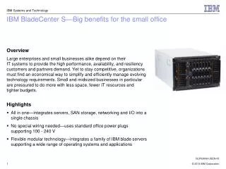
Dynamic infrastructure: IBM BladeCenter • Reduce cost • x86 industry-leading performance, virtualization, energy efficiency, and scalability • Manage risk • Resilient architectures and management tools for security and high availability • Improve service • Performance to drive new demanding application workloads
BladeCenter chassis components • BladeCenter chassis • BladeCenter chassis midplane • Power • Cooling • Unit summary
IBM BladeCenter family BladeCenter chassis by model and type IBM BladeCenter E Highest density, super power efficient IBM BladeCenter T Highly rugged, Telco, AC/DC, NEBS, air filtration IBM BladeCenter H Ultra high performance, and I/O flexibility IBM BladeCenter HT Highly rugged, Telco, AC/DC, NEBS, air filtration IBM BladeCenter S Extending the benefits of BladeCenter outside the datacenter • 8U design • Up to 8 blade bays • Up to 4 switch fabrics • AC or DC models • NEBS compliant • Rugged • Support 10 GB uplinks • Support 8 Gb FC • Telco, military, dirty floor • 7U design • Up to 14 blade bays • Up to 4 switch fabrics • Low cost • Low power • Support 10 GB Uplinks • Support 8 Gb FC • 9U design • Up to 14 blade bays • Up to 10 GB midplane • I/O flexibility up to 8 switch bays • Support 3 0mm blades w/ up to 8 ports • Support 10 GB Ethernet • Support 8 Gb FC • Support 4x InfiniBand • 12U design • Up to 12 blade bays • AC or DC models • I/O flexibility up to 8 switch bays • NEBS compliant • Rugged • Up to 10 GB midplane • Support 10 GB Ethernet • Support 8 Gb FC • Support 4x InfiniBand • Telco, military, dirty floor • 7U design • Up to 6 blade bays • Integrated storage • Up to 3 switch fabrics • Lowest cost • Lowest power (100 - 240v) • 950w/1450 AC auto-sensing • Support 10 GB Uplinks • Support 4 GB FC Common blades, common switches, common management
7U rack based mechanical One Midplane board Interface for major system components Divided into top and bottom halves Each half of the midplane is part of a redundant pair Front of chassis 14 hot-swap blade server bays One front control panel/media tray LED panel Media tray One USB port One DVD-RW Rear of chassis Four switch module bays Two management module bays Four hot-swap power supply module bays Two hot swap blowers Chassis: IBM BladeCenter E
IBM BladeCenter E: Front view Over-Temp Information System error Location Recess for chassis service label DVD-RW drive Power USB port Blade server filler Front panel LEDs and USB port CD-ROM drive Diskette drive 7U Blade server
IBM BladeCenter E: Rear view Power Module Bay 3 with PFA Switch Module Bay 1 Power Module Bay 1 with PFA Switch Module Bay 3 Hot-Swap Management Module (Optional) Hot-Swap Redundant Management Module Switch Module Bay 4 Power Module Bay 2 with PFA Switch Module Bay 2 Power Module Bay 4 with PFA IBM Calibrated Vectored Cooling Hot-Swap Redundant Blowers with PFA LED Panel
IBM BladeCenter E: Rear view (new chassis) IBM BladeCenter E with 2320W Power Supply Modules
Chassis: IBM BladeCenter T • 8U and 28 inches deep • Supports up to eight blade servers • Up to four double slot blade servers • Hot swappable media tray • 24X DVD/CD drive • Telco alarm panel • Two USB front inputs • Supports up to two management modules • Four front load balancing and failover 1300W AC or DC power supplies • Each power supply contains two fans and a LED panel • Four rear I/O modules • Four rear blower modules • KVM module • LAN module
IBM BladeCenter T: Front view Management Module bay 2 Management Module 1 Power Module 2 Power Module 1 From top to bottom Blade servers 1-8 Power Module 3 Power Module 4 ESD connector Media tray Front panel
IBM BladeCenter T: Rear view I/O Module 2 I/O Module 1 Blower Module 1 Blower Module 2 AC-power connectors (8730) or DC-power connectors (8720) Blower Module 3 Blower Module 4 I/O Module 4 ESD connector I/O Module 3 KVM Module LAN Module
Chassis: IBM BladeCenter H • 9U and 28 inches deep • Supports up to 14 30 mm blades • Customer serviceable, hot swappable media tray • 9.5 mm combo drive (CD/DVD) • Two USB front inputs • Full light path diagnostics panel • Rack mounted on rails • Four front load 2900W power supplies • Each power supply includes a replaceable fan pack with three fans
IBM BladeCenter H: Front view Two bays for Hot-Swap Redundant 2900 Watt Power Supply with PFA and three replaceable fans each 9U Hot-Swap Media Tray with DVD, 2 USB, and LightPath Diagnostics Panel Support for up to 14 Blades Two bays for optional Hot-Swap Redundant 2900 Watt Power Supplies with PFA and three replaceable fans each
IBM BladeCenter H: Rear view Redundant Power Input High Speed Switch Module Bays Redundant Power Input Hot-Swap Advanced Management Module (AMM) Switch Module Bay 1 (dedicated Ethernet) Dedicated Bridge Module Slot Switch Module Bay 3 (or Bridge Slot) (Optional) Hot-Swap Redundant Advanced Management Module (AMM) Switch Module Bay 2 (dedicated Ethernet) Dedicated Bridge Module Slot Switch Module Bay 4 (or Bridge Slot) LightPath Diagnostics Panel Aggregated Serial Connector IBM Calibrated Vectored Cooling Hot-Swap Redundant Blowers with PFA High Speed Switch Module Bays
Chassis: IBM BladeCenter HT • 12U and 27.8 inches deep • Supports up to 12 blade servers • Up to six double slot blade servers • Support up to two media trays • Full Light Path Diagnostic panel • Two USB front inputs • Support up to four front 3160W AC or DC power supplies with load balancing and failover • Each power supply contains a replaceable fan pack with three fans • Four I/O module bays • Four high-speed I/O module bays • Four rear blower modules • Supports up to two multiplexer expansion module
IBM BladeCenter HT: Front view Power Module bay 3 Power Module 1 High-speed I/O Module bay 7 Media tray bay 1 Management Module 1 High-speed I/O Module bay 8 I/O Module bay 1 I/O Module bay 3 ESD connector From left to right Blade servers 1-12 I/O Module bay 2 I/O Module bay 4 High-speed I/O Module bay 9 Management Module 2 Media tray bay 2 High-speed I/O Module bay 10 Power Module 2 Power Module bay 4
IBM BladeCenter HT: Rear view Network-clock bay 2 Power connector 1 Power connector 3 Network-clock bay 1 Multiplexer expansion module 1 Fan Module 3 Fan Module 1 Fan Module 4 Fan Module 2 Multiplexer expansion module 2 Alarm panel module Power connector 2 Power connector 4 Serial connector Alarm panel interface connector
Chassis: IBM BladeCenter S • Supports up to six 30 mm blades • Hot swappable media tray • Light Path Diagnostics panel • Combo drive (CD/DVD) • Two optional battery backup units • Two USB 2.0 ports • Two 950-watt/1450 auto-sensing power supplies • Express model comes with four 950-watt/1450 power supplies • Four hot-swap fan packs • Two optional integrated Disk Storage Modules (DSM) • Up to twelve 3.5-inch HS HDDs per shuttle • One Advanced Management Module
IBM BladeCenter S: Front view Ideal for tiered workloads; SAS and SATA disks can be mixed in BladeCenter S using RAID 0, 1, and 10 7U Easy access to shared USB portsand UltraBay Battery Backup Units for use with IBM BladeCenter SAS Connectivity Module Ideal for business-in-a-box configurations, legacy & future servers supported
IBM BladeCenter S: Rear view BladeCenter S Express Model Power Supplies 3 and 4 are optional, Auto-sensing b/w 950W 100/110V or 1450W 220/240v AMM standard Serial module option Four hot-swap fan pack standard Top and bottom right: I/O modules Bottom left: For future use Power Supplies 3 and 4 are included in Express, Auto-sensing b/w 950W 100/110V or 1450W 220/240v
BladeCenter chassis components • BladeCenter chassis • BladeCenter chassis midplane • Power • Cooling • Unit summary
BladeCenter: Interior view Upper Processor blade connectors Lower Upper midplane half Lower midplane half BladeCenter H example
BladeCenter: Midplane Power module connector Power module connector 1X fabric and controls Blade power connector Media tray alignment pin Media tray connector 4X fabrics 1X fabric and controls Blade power connector Power module connector Power module connector Rear LED and serial connector BladeCenter H example
BladeCenter chassis BladeCenter chassis midplane Power Cooling Unit summary BladeCenter chassis components BC-E Power Module BC-H Power Module
IBM BladeCenter E: Power components Power supply: • 2000 W or 2320 W AC/DC hot-swap redundant power modules • Maximum of four power modules supported • AC and DC LEDS on each power module • 200-240 V AC (range: 180-265 V AC) • Load balancing across all power supplies • Built-in overload and surge protection • Cooling is provided by the host system Optional Power Supplies 3 and 4 Power Supplies 1 and 2 Left Redundant Pair • Optional • Operate as redundant pair • Provides redundant power for blades 7-14 • Load balancing power supplies Right Redundant Pair • Standard with chassis • Operate as redundant pair • Provides redundant power for chassis modules and blades 1-6 • Load balancing power supplies
IBM BladeCenter E: Specifics and considerations • Two power supplies in bays 1 and 2 standard • Two 9ft IEC 320-C13 to C14 or two IEC 320-C19 to C20 cables for intra-rack power distribution) • Max: four hot-swap power supplies • Rear access • 2000 or 2320 watts at 220v • Both redundant (N+N redundancy) / two std modules supply power to all modules and blade bays 1 through 6 • Power for bays 7 through 14 requires two additional power modules in bays 3 and 4 (redundant to each other) • Voltage-sensing • Auto-restart • No fans power in module(s) IBM BladeCenter E Power Supply C19 to C20 Power Cord
BladeCenter H: Power components BladeCenter H power supplies • Each vertical pair is N+N redundant PowerConnector 2 PowerConnector 1
BladeCenter H: Power modules • Power module bays • Maximum of four per chassis • Two ship standard with the chassis
Two power supplies in bays 1 and 2 standard Max: Four hot-swap power supplies Front access Two IEC320 for the M/T 8720 (DC power) Input voltage range -48V - 60V (Min/Max) at 50/60Hz IBM BladeCenter T 8720 should be attached to the appropriate DC wiring Two IEC320 for the M/T for the 8730 (AC power) Input voltage range 180VAC - 264VAC (Min/Max) at 50/60Hz IBM BladeCenter T 8730 should be attached to high-voltage PDUs C14 male appliance connector 1300 watts Two standard modules (in slots 1 and 2) supply power to switch bays 1 and 2, both management modules, blade bays 1 - 4 and media tray Two additional power modules provide full system redundant power and power to switch bays 3 and 4, and blade bays 5 - 8 All: Load balancing / voltage-sensing / auto-restart IBM BladeCenter T: Power components IBM BladeCenter T DC power supply IBM BladeCenter T AC power supply
IBM BladeCenter HT: Power components • Two standard power supplies ships with the BladeCenter • Max: four hot-swap power supplies • Front access • IBM BladeCenter HT 8740 (DC Power Input voltage range -48VDC to -60VDC (Min/Max) • IBM BladeCenter HT 8750 (AC Power input voltage range -48VDC to -60VDC (Min/Max) at 50/60Hz • Redundant within pair (N+N redundancy) / power modules 1 and 2 support blade bays 1- 6, all legacy switch and bridge modules, upper and lower media trays, both advanced management modules, multiplexer expansion modules and alarm panel module • Power modules 3 and 4 support blade bays 7-12 and all high speed switch modules • Auto-restart • Three fans per power module IBM BladeCenter HT Power Supply
IBM BladeCenter S: Power components • Two standard power supplies ships with the BladeCenter • Maximum four hot-swap • Rear access • 1450 watts at 220V • 950 watts at 110V • Redundant within pair (N+N redundancy) • Voltage-sensing • Auto-restart • Two fans per power module • Modules 1 and 2 standard • Modules 3 and 4 required with 2nd Storage module installed
BladeCenter chassis components: Cooling BladeCenter chassis BladeCenter chassis midplane Power Cooling Unit summary
BladeCenter E: Cooling subsystem Two blowers Capable of 325 cubic feet per minute (CFM) each 150 CFM each in standard operation Hot swap, redundant Air flow is from the front to rear Fan speed control Predictive blower failure by monitoring the blower RPM Back flow dampers shall be incorporated to prevent air short circuiting if one blower fails
IBM BladeCenter H: Cooling subsystem Hot-swap customer serviceable AC blower units Hot-swap customer serviceable fan packs BladeCenter H front chassis BladeCenter H rear chassis IBM BladeCenter H blower Hot-swap customer serviceable fan pack
IBM BladeCenter T: Cooling subsystem • Four blowers comes standard • Maximum four • 3+1 redundancy configuration • Calibrated vectored cooling • Hot-swap • Redundant • Variable speed • Rear access • 330 cubic ft per min (CFM) • Front to back airflow; filtered air intake BC T Rear Chassis BC T Blower Unit (1) of (4)
IBM BladeCenter HT: Cooling subsystem • Four hot-swap blowers standard/Maximum • N+1 cooling redundancy • Speed controlled according to ambient air temperature • Rear access • Front to back airflow
IBM BladeCenter S: Cooling subsystem • Four hot-swap fans standard • N+1 redundant cooling airflow • Throttled according to incoming air temperature • Rear access • Front to back airflow
Key words • Advanced Management Module (AMM) • Concurrent Keyboard, Video and Mouse (cKVM) • Disk Storage Module (DSM) • Dynamic Infrastructure (DI) • Keyboard, Video, Mouse (KVM) • IBM BladeCenter E (Enterprise) • IBM BladeCenter H (High Performance) • IBM BladeCenter HT (High Performance Telco) • IBM BladeCenter S (Simplification) • IBM BladeCenter T (Telco) • Local Area Network (LAN) • Network Equipment Building System (NEBS)
The IBM BladeCenter contains a redundant circuit path to connect all blades servers to the AMM and switching fabric through which of the following: Blade servers are interconnected by a system of shielded cabling A Midplane, with redundant upper and lower halves, connects all blade servers and provides a path to the switching modules Each blades server is independently connected to the AMM and switching modules True/False: The Midplane for the BladeCenter H contains only the new high-speed 4x signaling fabric connectors. The IBM BladeCenter E Chassis supports up to 14 Blade Servers. With Power Supplies 1 and 2 installed, which blade servers, switch modules and management modules will receive power? All fourteen Blade Server slots, all four switch module slots, the two blowers, the two management module slots and the media tray. Blade Server slots 1 through 6, all four switch module slots, the two blowers, the two management module slots and the media tray. Blade Server slots 1 through 6, switch module slots one and two, one management module slot and the media tray. All fourteen Blade Server slots and the management module slots, the two blowers, and the media tray. Checkpoint (1 of 3)
Checkpoint solutions (1 of 3) • The IBM BladeCenter contains a redundant circuit path to connect all blades servers to the AMM and switching fabric through which of the following: • Blade servers are interconnected by a system of shielded cabling • A Midplane, with redundant upper and lower halves, connects all blade servers and provides a path to the switching modules • Each blades server is independently connected to the AMM and switching modules Answer: b • True/False: The Midplane for the BladeCenter H contains only the new high-speed 4x signaling fabric connectors. Answer: False • The IBM BladeCenter E Chassis supports up to 14 Blade Servers. With Power Supplies 1 and 2 installed, which blade servers, switch modules and management modules will receive power? • All fourteen Blade Server slots, all four switch module slots, the two blowers, the two management module slots and the media tray. • Blade Server slots 1 through 6, all four switch module slots, the two blowers, the two management module slots and the media tray. • Blade Server slots 1 through 6, switch module slots one and two, one management module slot and the media tray. • All fourteen Blade Server slots and the management module slots, the two blowers, and the media tray. Answer: b
Checkpoint (2 of 3) • True/False: All models of the BladeCenter implement common power, cooling and signaling paths for multiple Blade Servers. • True/False: In addition to component cooling, each BladeCenter provides general chassis cooling through blowers. • Select the correct statement regarding power input to the BladeCenter S chassis. • The BladeCenter S chassis requires 220/240V power • The BladeCenter S can be ordered with 110V input as an option • The BladeCenter S supports (2) power supplies maximum at 100/110V • The BladeCenter S supports either 100/110V or 220/240V input • Operator information indicating warnings for over temperature and system error is viewed on the BladeCenter E chassis through which of the following methods? • The front panel of each blade server • On the Light Path panel on the media tray • On the Light Path display on the lower rear of the chassis • On the AMM module • Both b and c • Which statement is correct regarding BladeCenter S power modules? • Standard power supplies 1 and 2 support 3 blade servers • Four power modules are shipped with the base BladeCenter S chassis • Optional power supplies 3 and 4 are required for the second Disk Storage Module • Optional power supplies 3 and 4 are required for I/O bays 1 and 3
Checkpoint solutions (2 of 3) • True/False: All models of the BladeCenter implement common power, cooling and signaling paths for multiple Blade Servers. Answer: True • True/False: In addition to component cooling, each BladeCenter provides general chassis cooling through blowers. Answer: True • Select the correct statement regarding power input to the BladeCenter S chassis. • The BladeCenter S chassis requires 220/240V power • The BladeCenter S can be ordered with 110V input as an option • The BladeCenter S supports (2) power supplies maximum at 100/110V • The BladeCenter S supports either 100/110V or 220/240V input Answer: d • Operator information indicating warnings for over temperature and system error is viewed on the BladeCenter E chassis through which of the following methods? • The front panel of each blade server • On the Light Path panel on the media tray • On the Light Path display on the lower rear of the chassis • On the AMM module • Both b and c Answer: e • Which statement is correct regarding BladeCenter S power modules? • Standard power supplies 1 and 2 support 3 blade servers • Four power modules are shipped with the base BladeCenter S chassis • Optional power supplies 3 and 4 are required for the second Disk Storage Module • Optional power supplies 3 and 4 are required for I/O bays 1 and 3 Answer: c
Checkpoint (3 of 3) • True/False: The BladeCenter S Disk Subsystem supports a combination of SAS and SATA drives. • True/False: IBM BladeCenter E contains 10 I/O module bays and supports I/O network switching for storage switches, pass through devices, traditional fabrics, and high-speed fabrics. • True/False: For Telco maintenance, the BladeCenter HT chassis supports up to 4 hot-swap and redundant DC or AC power supply modules with load-balancing and failover capabilities located in the rear of the chassis • Which chassis was designed specifically for telecommunications network infrastructures to support a highly rugged environments using air filtration? • BladeCenter S and BladeCenter E • BladeCenter T and BladeCenter HT • BladeCenter E and BladeCenter H • BladeCenter H and BladeCenter HT
Checkpoint solutions (3 of 3) • True/False: The BladeCenter S Disk Subsystem supports a combination of SAS and SATA drives. Answer: True • True/False: IBM BladeCenter E contains 10 I/O module bays and supports I/O network switching for storage switches, pass through devices, traditional fabrics, and high-speed fabrics. Answer: False • True/False: For Telco maintenance, the BladeCenter HT chassis supports up to 4 hot-swap and redundant DC or AC power supply modules with load-balancing and failover capabilities located in the rear of the chassis Answer: False • Which chassis was designed specifically for telecommunications network infrastructures to support a highly rugged environments using air filtration? • BladeCenter S and BladeCenter E • BladeCenter T and BladeCenter HT • BladeCenter E and BladeCenter H • BladeCenter H and BladeCenter HT Answer: b
Unit summary Having completing this unit, you should be able to: • List the major elements common to the IBM BladeCenter • Describe the key aspects of compatibility between BladeCenter models • Identify the components providing redundancy in the BladeCenter chassis • Match the power components necessary to support varying BladeCenter resource configurations • List the power input requirements for the BladeCenter models • Describe the common cooling components used in the BladeCenter chassis • Describe the supported disk configurations for the BladeCenter S