Design Overview of the ATLAS Absolute Luminosity Monitor: ALFA System Electronics
180 likes | 309 Vues
This document provides a detailed overview of the ATLAS Absolute Luminosity Monitor (ALFA) system, focusing on its electronic design and functionality. Developed at CERN, the ALFA system utilizes a scintillating fiber tracker for precise luminosity measurements at the LHC. Key components include the MAROC2 ASIC and FPGA technologies, facilitating data acquisition and signal processing. The paper discusses interconnections, data transmission techniques, and the configuration of front-end electronics, ensuring accurate performance in a challenging environment.

Design Overview of the ATLAS Absolute Luminosity Monitor: ALFA System Electronics
E N D
Presentation Transcript
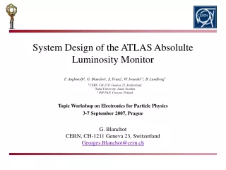
System Design of the ATLAS Absolulte Luminosity MonitorG. BlanchotCERN, CH-1211 Geneva 23, SwitzerlandGeorges.Blanchot@cern.ch F. Anghinolfi1, G. Blanchot1, S. Franz1, W. Iwanski1,3, B. Lundberg2 1CERN, CH-1211 Geneva 23, Switzerland2Lund University, Lund, Sweden3 INP PAN, Cracow, Poland Topic Workshop on Electronics for Particle Physics3-7 September 2007, Prague
Roman Pot locations ALFA: Absolute Luminosity For ATLAS 240 m G. Blanchot, CERN
The ALFA Scintillating Fiber Tracker The 20x64 fibres are read out by MA-PMT (R7600-M64 from Hamamatsu) G. Blanchot, CERN
The Roman Pot Assembly G. Blanchot, CERN
HV LV TTC Trigger Data Mother board FE FE FE FE FE MAPMT MAPMT MAPMT MAPMT MAPMT Photo Multiplier Front-End (PMF) B. Lundberg, University of Lund, Sweden. G. Blanchot, CERN
PMF Kapton Interconnections First version based on flat cable tested in 2006. Kapton interconnects is designed and under comstruction at LAL-Orsay. Need to fit a 60 pin connector to a flat cable in a width of about 30mm. The flat cable is driven by the motherboard. The interconnection system must allow for misalignments between PMFs. G. Blanchot, CERN
MAROC2 (ASIC) ALFA-R (FPGA) CLK40 LVL1A SPI DATA BUS Preamp Discri Readout System PMT 64 64 Front-End Configuration Stream Register 3 The ALFA Front-End Electronics (PMFE) MAROC Chip bonded to PMFE ALFA-R FPGA (BGA) on the back of the PMFE G. Blanchot, CERN
To ALFA-R Hold1 signal Hold2 signal Variable Slow Shaper 20ns-100ns S&H MUX Multiplexed charge output S&H ADC output 12bits Wilkinson ADC Photons Preamp. Gain correction (6bits) DC_FS Fast Shaper Bipolaire EN_serialiser Photomultiplicator 64 channels FS_choice 64 Trigger outputs 80MHz Encoder LUCID cmd_LUCID Fast Shaper Unipolaire LUCID 3 DACs 12 bits 3 discriminator thresholds (3*12bits) SUM of 7 fibers 9 Sums MAROC2 Front-End To configure the MAROC front-end chip, a stream of 538 bits must be serially shifted into it. Refer to: “MAROC: Multi Anode Readout Chip”, S. Blin, TWEPP 2007. G. Blanchot, CERN
ALFA Motherboard Motherboard Data PMFBus GOL Fiber ALFA-M GOL PMF-Row To 5 PMF Clk40 TTC Fiber QPLL TTCrx PMF-Row To 5 PMF LVL1A BCCnt EvnCnt 5VDC Power Regulators PMF-Row To 5 PMF 12VDC PMF-Row To 5 PMF V, I, HV Monitor Reset ELMB CANBus SPI Interface PMF-Row To 5 PMF G. Blanchot, CERN
SPI Communication with an ELMB • Each PMF needs 538 bits of configuration, 25 PMFs -> 13 450 bits. • An ELMB is provided to configure the RP front-end independently of the TTC status. • IO ports were discarded because of the limited bit rate (<100 bps, > 2 min. uploading). • SPI port was tested for a rate of 12 msec/ 32 bits frame, allowing to upload the configuration much faster (few seconds). • SPI port was easily implemented in ALFA-R and ALFA-M allowing to set some registers of the FPGAs and to monitor a Status register. SPI_CLK /SPI_CS SPI_DIN SPI_DIN 32 bits frame Write Cycle Read Cycle 12 msec Write Cycle 17 msecRead Cycle With the support of S. Franz from ATLAS DCS. G. Blanchot, CERN
SPI Frame Format • Motherboard registers: • Control, Status. • PMF registers: • Control, Status. • Masks. • Configuration Stream. G. Blanchot, CERN
Stream Configuration of PMFs ALFA-R SPI Shift Register SPI Bus Address, Offset Data Decoder Stream Register /EN D2 D1 D0 The MAROC front-end chip is configured through a serial interface: a reset pulse intiates the configuration, then all the configuration bits are shifted and validated by a clock. The configuration is sent on SPI from the ELMB, a stream of 3 bits configuration vectors are passed. The entire configuration is passed within few seconds. Refer to: “FPGA based Readout Logic of the Front-end Electronics of the Absolute Luminosity Monitor”, W. Iwanski, TWEPP 2007. G. Blanchot, CERN
Reset commands for FPGA Tools to prepare the setup of the PMFs Launch configuration of PMF(s) Tool to store configuration in text file Tool to copy configuration from one PMF to another one Status of software / hardware Write/read commands PMFs Configuration from DCS With the support of S. Franz from ATLAS DCS. G. Blanchot, CERN
Status Register of Motherboard • The Status register is the only register on the ALFA-M FPGA available in the DCS through the SPI port of the ELMB. • It allows monitoring the status of key elements in the system: • Bit 15 – Test_Mode: indicates if the ALFA-M is running a test sequence. • Bit 14 – GOL_Ready: if set, the GOL is ready to transmit data. • Bit 13 – TTC_Ready: if set, the TTC is receiving signal and is driving the clock. • Bit 12 – QPLL_Error: if set, the QPLL is not initialized correctly. • Bit 11 – QPLL_Lock: if set, the QPLL is driving a stabilized clock on a locked phased. G. Blanchot, CERN
ALFA-R (PMF) ALFA-M (MB) Pipeline Data Transmission 5x5 times 25 times L1A Event Format GOL Fiber1.6 Gbps 64bits DeRand. 5x5 times Shift Regs. GOL. FIFO L1Cnt BCCnt • Data (64 bits) is stored at 40MHz in a pipeline together with a local BC counter (4 bits). • When L1A is driven, the derandomizer fetches the event from the pipeline, and it adds L1 counter information (3 bits). • The 71 bits stored in the derandomizer are move serially at 40 MHz into a shift register of the motherboard. • The L1A process requires about 80 clock cycles. • The content of the 25 shift registers is combined together to form. • BCCnt and EvCnt are compared to validate the data of each register. • A framed event is built with header, data and end of frame 32 bits words. • The event’ words are pushed into an output FIFO. • The GOL fetches the data available in the FIFO and transmits it over the fiber. • The framed event can be received by any GOL compatible receiver. • For testbeams, a FILAR card plugged into a PC is used. • In ATLAS, a GOL compatible ROD will be used to build ATLAS events from the eight incoming fibers. Refer to: “FPGA based Readout Logic of the Front-end Electronics of the Absolute Luminosity Monitor”, W. Iwanski, TWEPP 2007. G. Blanchot, CERN
Framed Data • The data from each PMF validated by a L1A signal is framed to form an event by the ALFA-M FPGA: • Fixed SOF and EOF words delimit the beginning and the end of the frame. • BCID and EVNTCNT from the TTCrx chip is appended. • The error flags that resulted from the comparison of local BC and Event counters are appended. • The number of PMFs that conform the setup is appended. • All PMF information (2 words per PMF) follows. • Finally a parity word is appended for error tracking on the back-end. G. Blanchot, CERN
Testbeam at CERN October 2006 PMFs 2x2x64 + Final Trig. Overlap Detectors Mother Board • Detectors • Two ALFA trackers. • Overlap Detectors • Beam • 230 GeV protons (p+/-) Tracker 2x10x16 • Setup • 5 x PMF - Motherboard – FILAR PC G. Blanchot, CERN
Conclusions • A prototype for the front-end electronics of the ATLAS Roman Pots was built and succesfully tested on a testbeam in 2006, new version is under development right now. • A readout chain was designed to handle the data of 25 front-end chips and to send it into a single GOL fiber. • The system is independently controlled by an embedded ELMB that allows full integration and reliable control from DCS. • A data format was defined and is embedded on a FPGA, providing a data flow that can be handled in a ROD. G. Blanchot, CERN