Modeling Unwanted and Blocking Interference Modes in Telecommunications
240 likes | 362 Vues
This document presents a comprehensive analysis of unwanted emissions and blocking interference modes in telecommunications, focusing on calculations and criteria essential for effective interference management. It explores the impact of interfering systems on victim receivers and provides simulation results using SEAMCAT. Key aspects include the definition of emission masks, interference protection ratios, and the interactions between different interference types. Additionally, it addresses practical questions regarding simulation setup. This work is crucial for ensuring reliable communication in the presence of various interference challenges.

Modeling Unwanted and Blocking Interference Modes in Telecommunications
E N D
Presentation Transcript
Modeling ofUnwanted and Blocking Interference Modes European Communications Office Jean-Philippe Kermoal 05 October 2010
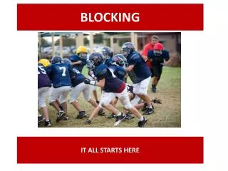
Interfering Modes • Unwanted Emissions Case • Blocking Case
Interference Calculations Interference Criteria Interfering Modes Unwanted and Blocking Signals
Interferer emission mask fI Unwanted Emissions • Victim Receiver Bandwidth fv • Interfering System Interfering emission mask fI
Victim Link Frequency
Victim Link / Victim Receiver Interference Criterion Reception bandwidth
Interfering Link Frequency
Interfering Link/Interfering transmitter Power Emission Mask
Interfering Link/Interfering transmitter/Unwanted emissions mask Default value erroneous value See the following presentations...
Interfering Link/Victim receiver -> Interfering transmitter Path Att = + 32.4 + 20 x log (f (MHz)) + 20 x log (d (km)) Att = + 32.4 + 20 x log (900 MHz) + 20 x log (10 km) Att = + 111.5 dB
Simulations... 10 km IRSS Unwanted = P in the victim bandwidth + Ge + Gr – Att (free space)IRSS Unwanted = 12 dBm + 0 dB + 0 dB – 111.5 dBIRSS Unwanted = - 99.5 dBm
Results N = -110 dBmIRSS Unwanted = -99.5 dBmI/N = -99.5 – (-110) = 10.5 dB ( Calculated by SEAMCAT)Interference Criterion was: I/N = 0 ( Input to SEAMCAT)
Results... I/N=0dB Pe = 22.5 dBm
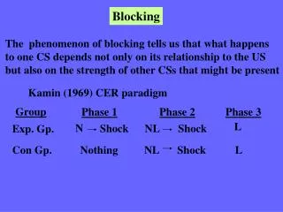
Blocking • Victim Receiver Bandwidth Rejection of the receiver fv fI • Interfering System Interferer fI
Blocking: 3 Modes User Defined (dB): Rejection at the receiverAttBlocking = BlockUD Protection Ratio (dB):AttBlocking = BlockPR + C/(N+I) + 3 dB Sensitivity Mode (dBm): Maximum Acceptable Value of PowerAttBlocking = BlockSens (dBm) – Sensitivity (dBm) + C/(N+I)
But not so different • Protection Ratio:Interfering Blocking Level = Pe + Ge + Gr – Att – AttBlockingWhere: AttBlocking = BlockPR + C/(N+I) + 3 dB • If C/(N+I) = - 3 dB AttBlocking = BlockPR - 3 dB + 3 dB = BlockPR • ....equivalent to User Defined Mode • If C/I = 0 dBBroadcast PR Mode...
fV fI Blocking Mask Should be defined at the frequency of the Interferer Att blocking = 50 dB (e.g. Defined in ETSI Standards)
Simulations IRSS Blocking= Pe + Ge + Gr – Att (free space) – Att blockIRSS Blocking= 33 dBm + 0 dB + 0 dB – 111.5 dB – 50 dBIRSS Blocking = - 128.5 dBm
Results IRSS Blocking Level = - 128.5 dBmN = -110 dBmI/N = 0 dB (Criterion) always met
Question? • Can I make simulation for unwanted and blocking in the same workspace?
Question: Can I make simulation for unwanted and blocking in the same workspace? • 2 Interference Criteria / 2 runs
Question: Can I run simulations for unwanted and blocking in the same workspace in a single run? If the interference criteria are not the same... You can compensate this when defining the mask (unwanted or blocking) Blocking: PR mode + Criterion: C/I=0 dB Unwanted: Criterion C/I=10 dB Remove 10 dB from blocking mask Criterion C/I=10 dB
Questions? • Thanks for your attention