An Embedded Software Primer
Explore Round-Robin, Function-Queue-Scheduling, and RTOS Architectures using code examples and real-world applications. Learn about pros and cons to help you choose the right architecture for your embedded system.


An Embedded Software Primer
E N D
Presentation Transcript
An Embedded Software Primer David E. Simon
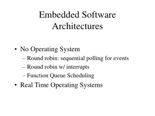
Chapter 5: Survey of Software Architectures • Round-Robin • Round-Robin with Interrupts • Function-Queue-Scheduling Architecture • Real-Time Operating System Architecture • Selecting an Architecture
Round-Robin • The following code (Fig. 5.1 Simon) illustrates a round-robin where the code checks each I/O device in turn and services them as needed.
Round-Robin (contd.) • This is the simplest architecture devoid of interrupts or shared-data concerns. • A digital multimeter illustrates this. • A pseudo-code written for it would consist of a switch-case loop that performs functions based on the position of the rotary switch. • However several problems offset its simplicity advantage:- • If a device has a lower response time this architecture won’t work. e.g. if in Fig. 5.1 device Z has a deadline of 15 ms and A and B take 10 ms each. • If any one of the cases for the multimeter could at the worst take 5 seconds, the system would have a max. response time of 5 seconds, which would make it less appealing. • Architecture is not robust. Addition of a single device might cause all deadlines to be missed.
Round-Robin with Interrupts • Fig. 5.4 shows a round-robin with interrupts.
Round-Robin with Interrupts (contd.) • ISRs called by each device set flags. These are in turn polled by the main program that then does the required follow-up processing. • ISRs can be assigned priorities as per the requirements giving better response especially for devices with hard deadlines. • The disadvantage is the complexity of having to work with the shared-data variables. Examples: A Simple Bridge • A communication bridge is a simple example that passes data between 2 ports. • Assume the bridge encrypts data at one port and decrypts it at the other (Fig. 5.6).
Round-Robin with Interrupts (contd.) • A character received at one of the bridge links causes an interrupt that must be serviced before the next character arrives. • The link will be busy while sending a character after which it will interrupt the microprocessor to indicate it is ready for the next character. • Routines read and write characters to queues and check whether the queues is empty or not. • Encryption and decryption is handled by routines. • Fig. 5.7 shows the code. • Transmitting and receiving characters on links A and B are handled by separate ISRs. • vEncrypt and vDecrypt in main read the data queues and pass the processed data to qDataToLinkA and qDataToLinkB. • fLinkAReadyToSend and fLinkBReadyToSend track whether I/O is ready to send characters. • Note that shared-data sections are made atomic. • As reading and writing is done in ISRs, these have higher priority than the encryption or decryption, so a sudden character burst will not cause system overruns.
Round-Robin with Interrupts (contd.) Characteristics of the Round-Robin with Interrupts • The main shortcoming of this architecture is that all the task code executes with the same priority. • If devices A,B and C in fig. 5.4 take 200 ms, C will have to wait 400 ms. • This can be avoided by moving C’s task code to the ISR at the expense of increased interrupt latency of lower priority devices. • Another solution is to check C’s flag more often like A,C,B,C,D,C....... • The worst-case response for a device task-code occurs when the its interrupt occurs immediately after main passes its task code. • Examples where this architecture does not work are :- • A laser printer. Calculating locations for the black dots is time consuming so only ISRs will get good response. If task codes are moved into ISRs low priority interrupts will not be serviced fast enough. • Underground tank monitoring system. The code that calculates the gasoline amount hogs the processor.
Function-Queue-Scheduling Architecture • Fig. 5.8 shows an implementation of this architecture.
Function-Queue-Scheduling Architecture (contd.) • The ISRs add function pointers to a queue for main to call. • Main can call the functions based on a preset priority providing better response times for higher priority tasks • The worst-case response (WCR) for the highest priority task is equal to the longest task code function assuming that it started just before the ISR put the function pointer for the highest priority task in the queue. • This is much better than the round-robin-with-interrupts which has a WCR equal to the sum of all the task codes for the other devices. • A disadvantage of the architecture apart from the complexity involved is that a high priority task might hog the processor, and a lower priority task might never get to execute.
Real-Time Operating System Architecture • Fig. 5.9 shows the operation.
Real-Time Operating System Architecture (contd.) • Again ISRs handle important sections. • Some differences from previous architectures are :- • The real-time operating system (RTOS) handles communications between ISRs and task codes. • The RTOS will decide which task code to run based on urgency (priority) • RTOS can suspend a task to run another (usually higher priority) one. • If an ISR sets a flag for a higher priority task the RTOS runs the task immediately on return even if it is in the middle of another lower priority one. • Hence the worst-case response is zero. • Response is basically independent of task code length unlike previous architectures. Changes to code lengths of low priority tasks don’t affect higher priority tasks. • One disadvantage might be the added RTOS processing time.
Selecting an Architecture • Select the simplest architecture meeting response requirements. • RTOSs should be used where response requirements demand them. • Hybrid architectures can be used if required. e.g. you can use an RTOS with a low-priority task polling the relatively slower hardware.