Download
1 / 83
840 likes | 1.01k Vues
School of Computing Science Simon Fraser University CMPT 765/408: Computer Networks Networking Basics I Instructor: Dr. Mohamed Hefeeda. Course Objectives . Understand principles of designing and operating computer networks structure and protocols of the Internet

E N D
School of Computing Science Simon Fraser University CMPT 765/408: Computer Networks Networking Basics I Instructor: Dr. Mohamed Hefeeda
Course Objectives • Understand • principles of designing and operating computer networks • structure and protocols of the Internet • services that can/cannot be offered by the Internet • Know how to • analytically analyze performance of a system/protocol • implement network protocols and applications • And, more importantly, … • Have fun!
Course Info • Most of the course will be lectures given by the instructor • Last 2-3 weeks, each student presents a paper on one of the current hot topics • Course web page http://nsl.cs.surrey.sfu.ca/teaching/06/765/ Or access it from my web page: http://www.cs.sfu.ca/~mhefeeda
Course Info: Textbooks and References • All are on reserve in SFU Surrey Library • Kurose and Rose, Computer Networking: A top-down Approach Featuring the Internet, 2005 • Background materials • Chapters 6 and 7: Wireless and Multimedia Networking • Hassan and Jain, High Performance TCP/IP Networking, 2004 • Several chapters on analyzing TCP/IP in different environments • Stallings, High-speed Networks and Internets: Performance and Quality of Service, 2002 • Three chapters on (basics of) probability and queuing • Papers: will be posted on the course web page
Course Info: Grading • Homework: 20% • 3 – 4 problem sets • Projects: 35% • 4 projects; group of two students • Class participation:10% • Ask and answer questions • Present one chapter/paper • Final exam: 35% • Comprehensive
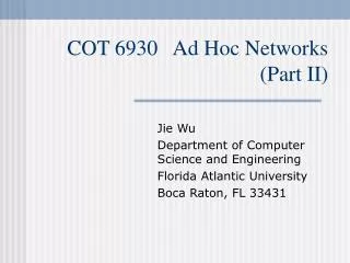
Course Info: Topics • Internet Architecture and Services • TCP/IP Protocol Suit • Inter- and Intra-domain Routing Protocols • Introduction to Performance Modeling and Evaluation • Introduction to Simulation and Measurement of Networked Systems • TCP/IP Performance Modeling in Different Environments • Quality of Service Support in the Internet • Wireless Networks • Multimedia Networking • Overlays and Peer-to-Peer Computing • Hot Topics • Mesh networks, sensor networks, P2P, denial of service attacks, security in wireless networks, …, you choose/propose
Review of Basic Networking Concepts • Internet structure • Protocol layering and encapsulation • Internet services and socket programming • Network Layer • Network types: Circuit switching, Packet switching • Addressing, Forwarding, Routing • Transport layer • Reliability and congestion control • TCP, UDP • Link Layer • Multiple Access Protocols • Ethernet
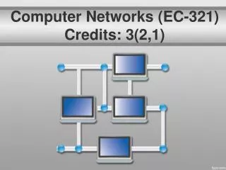
Millions of hosts (end systems) Inter-connected, running network apps Diverse communication links fiber, copper, radio, satellite Routers forward packets Internet:“network of networks” loosely hierarchical Public, versus private intranet router workstation server mobile local ISP regional ISP company network The Internet
roughly hierarchical at center: “tier-1” ISPs (e.g., MCI, Sprint, AT&T, Cable and Wireless), national/international coverage treat each other as equals NAP Tier-1 providers also interconnect at public network access points (NAPs) Tier-1 providers interconnect (peer) privately Internet structure: network of networks Tier 1 ISP Tier 1 ISP Tier 1 ISP
Seattle POP: point-of-presence DS3 (45 Mbps) OC3 (155 Mbps) OC12 (622 Mbps) OC48 (2.4 Gbps) Tacoma to/from backbone peering New York … …. Stockton Cheyenne Chicago Pennsauken Relay Wash. DC San Jose Roachdale Kansas City … … … Anaheim to/from customers Atlanta Fort Worth Orlando Tier-1 ISP: e.g., Sprint Sprint US backbone network
“Tier-2” ISPs: smaller (often regional) ISPs Connect to one or more tier-1 ISPs, possibly other tier-2 ISPs NAP Tier-2 ISPs also peer privately with each other, interconnect at NAP Tier-2 ISP pays tier-1 ISP for connectivity to rest of Internet Tier-2 ISP is customer of tier-1 provider Tier-2 ISP Tier-2 ISP Tier-2 ISP Tier-2 ISP Tier-2 ISP Internet structure: Tier-2 ISPs Tier 1 ISP Tier 1 ISP Tier 1 ISP
“Tier-3” ISPs and local ISPs last hop (“access”) network (closest to end systems) Tier 3 ISP local ISP local ISP local ISP local ISP local ISP local ISP local ISP local ISP NAP Local and tier- 3 ISPs are customers of higher tier ISPs connecting them to rest of Internet Tier-2 ISP Tier-2 ISP Tier-2 ISP Tier-2 ISP Tier-2 ISP Internet structure: Tier-3 ISPs Tier 1 ISP Tier 1 ISP Tier 1 ISP
a packet passes through many networks! Tier 3 ISP local ISP local ISP local ISP local ISP local ISP local ISP local ISP local ISP NAP Tier-2 ISP Tier-2 ISP Tier-2 ISP Tier-2 ISP Tier-2 ISP Internet structure: packet journey Tier 1 ISP Tier 1 ISP Tier 1 ISP
Review of Basic Networking Concepts • Internet structure • Protocol layering and encapsulation • Internet services and socket programming • Network Layer • Network types: Circuit switching, Packet switching • Addressing, Forwarding, Routing • Transport layer • Reliability and congestion control • TCP, UDP • Link Layer • Multiple Access Protocols • Ethernet
Networks are complex! many “pieces”: hosts routers links of various media applications protocols hardware, software Question: Is there any hope of organizing structure of network? Or at least our discussion of networks? Protocol Layers
ticket ticket (purchase) baggage (check) gates (load) runway (takeoff) airplane routing ticket (complain) baggage (claim gates (unload) runway (land) airplane routing baggage gate airplane routing airplane routing takeoff/landing airplane routing departure airport intermediate air-traffic control centers arrival airport Layering of Airline Functionality Layers: each layer implements a service • via its own internal-layer actions • relying on services provided by layer below
Why layering? Dealing with complex systems: • explicit structure allows identification, relationship of complex system’s pieces • modularization eases maintenance, updating of system • change of implementation of layer’s service transparent to rest of system • e.g., change in gate procedure doesn’t affect rest of system • What is the downside of layering?
application: supporting network applications FTP, SMTP, HTTP transport: host-host data transfer TCP, UDP network: routing of datagrams from source to destination IP, routing protocols link: data transfer between neighboring network elements PPP, Ethernet physical: bits “on the wire” application transport network link physical Internet protocol stack
source network link physical message application transport network link physical segment link physical M M Ht Ht M M switch Hn Hn Hn Hn Ht Ht Ht Ht M M M M Hl Hl Hl Hl Hl Hl Hn Hn Hn Hn Hn Hn Ht Ht Ht Ht Ht Ht M M M M M M destination application transport network link physical router Encapsulation datagram frame
Review of Basic Networking Concepts • Internet structure • Protocol layering and encapsulation • Internet services and socket programming • Network Layer • Network types: Circuit switching, Packet switching • Addressing, Forwarding, Routing • Transport layer • Reliability and congestion control • TCP, UDP • Link Layer • Multiple Access Protocols • Ethernet
Internet Services • View the Internet as a communication infrastructure that provides services to apps • Web, email, games, e-commerce, file sharing, … • Two communication services • Connectionless unreliable • Connection-oriented reliable
Connection-oriented Prepare for data transfer ahead of time establish connection setupstate in the two communicating hosts Usually comes with reliability, flow and congestion control TCP: Transmission Control Protocol Connectionless No connection set up, simply send Faster, less overhead No reliability, flow control, or congestion control UDP: User Datagram Protocol Internet Services How can we access these services?
host or server host or server process process socket socket TCP with buffers, variables TCP with buffers, variables Network (Socket) Programming • Process sends/receives messages to/from its socket • Socket analogous to door • sending process shoves message out door • sending process relies on transport infrastructure on other side of door which brings message to socket at receiving process controlled by app developer Internet controlled by OS • Socket is the interface (API) between application and transport layer
Review of Basic Networking Concepts • Internet structure • Protocol layering and encapsulation • Internet services and socket programming • Network Layer • Network types: Circuit switching, Packet switching • Addressing, Forwarding, Routing • Transport layer • Reliability and congestion control • TCP, UDP • Link Layer • Multiple Access Protocols • Ethernet
Mesh of interconnected routers The fundamental question: how is data transferred through net? circuit switching: dedicated circuit per call: telephone net packet-switching: data sent thru net in discrete “chunks” The Network Core
Network resources (e.g., bandwidth) divided into “pieces” using Frequency division multiplexing (FDM) Time division multiplexing (TDM) Pieces allocated to “calls” (connections) guaranteed performance Resource piece idle if not used by owning call no sharing Connection setup is required Examples (Traditional) Telephone network Network Core: Circuit Switching
each end-end data stream divided into packets packets from different users share network resources each packet uses full link bandwidth resources used asneeded store and forward: packets move one hop at a time Node receives complete packet before forwarding Bandwidth division into “pieces” Dedicated allocation Resource reservation Network Core: Packet Switching resource contention: • aggregate resource demand can exceed amount available • congestion: packets queue, wait for link use
Sequence of A & B packets does not have fixed pattern, shared on demand statistical multiplexing In contrast, in TDM each host gets same slot in revolving TDM frame D E Packet Switching: Statistical Multiplexing 10 Mb/s Ethernet C A statistical multiplexing 1.5 Mb/s B queue of packets waiting for output link
1 Mb/s link each user: 100 kb/s when “active” active 10% of time circuit-switching: 10 users packet switching: with 35 users, probability > 10 active less than 0 .0004 Packet switching allows more users to use network! N users 1 Mbps link Packet Switching: Efficiency Q: how did we get value 0.0004?
Advantages no call setup simpler resource sharing (statistical multiplexing) better resource utilization more users or faster transfer (a single user can use entire bw) Well suited for bursty traffic (typical in data networks) Disadvantages Congestion may occur packet delay and loss need protocols to control congestion and ensure reliable data transfer Packet Switching
Datagram network Example: The Internet Virtual-circuit network Examples: ATM (Asynchronous Transfer Mode), frame relay, X.25 Packet Switching: Two Classes
no call setup at network layer routers: no state about end-to-end connections no network-level concept of “connection” packets forwarded using destination host address packets between same source-dest pair may take different paths application transport network data link physical application transport network data link physical 1. Send data 2. Receive data Packet-switched Datagram Networks
Source-to-dest path behaves much like telephone circuit” performance-wise connection setup, teardown for each call before data can flow each packet carries VC identifier (not destination address) every router on source-dest path maintains state for each passing connection link, router resources (bandwidth, buffers) may be allocated to VC Examples: ATM (Asynchronous Transfer Mode), frame relay, X.25 Packet-switched VC Networks
Signaling protocols are used to setup, maintain, and teardown VCs Note: not widely used in the current Internet application transport network data link physical application transport network data link physical VC Networks: Connection Setup 6. Receive data 5. Data flow begins 4. Call connected 3. Accept call 1. Initiate call 2. incoming call
Telecommunication networks Packet-switched networks Circuit-switched networks FDM TDM Datagram Networks Networks with VCs Network Taxonomy
Review of Basic Networking Concepts • Internet structure • Protocol layering and encapsulation • Internet services and socket programming • Network Layer • Network types: Circuit switching, Packet switching • Addressing, Forwarding, Routing • Transport layer • Reliability and congestion control • TCP, UDP • Link Layer • Multiple Access Protocols • Ethernet
Network layer protocols in every host and router Network layer’s goal transport data from sending host to receiving host We focus on datagram networks (Internet) network data link physical network data link physical network data link physical network data link physical network data link physical network data link physical network data link physical network data link physical application transport network data link physical application transport network data link physical Network Layer
Host, router network layer functions: • ICMP protocol • error reporting • router “signaling” • IP protocol • addressing conventions • datagram format • packet handling conventions • Routing protocols • path selection • RIP, OSPF, BGP forwarding table Network Layer in the Internet Transport layer: TCP, UDP Network layer Link layer physical layer
routing algorithm local forwarding table header value output link 0100 0101 0111 1001 3 2 2 1 value in arriving packet’s header 1 0111 2 3 Routing vs. Forwarding • Routing • determine route taken by packets from source to destination • Routing algorithms, e.g., RIP, OSPF, BGP • Forwarding • move packets from router’s input to appropriate output • use forwarding table populated by routing algorithm • E.g., IP forwarding function
IP Datagram Format IP protocol version number 32 bits total datagram length (bytes) header length (bytes) type of service head. len ver length for fragmentation/ reassembly fragment offset Provides some QoS flgs 16-bit identifier max number remaining hops (decremented at each router) upper layer time to live Internet checksum 32 bit source IP address 32 bit destination IP address upper layer protocol to deliver payload to E.g. timestamp, record route taken, specify list of routers to visit. Options (if any) data (variable length, typically a TCP or UDP segment) IP ver 4.0
IP address: 32-bit identifier for each host, router networkinterface Represented in Dotted-decimal notation 223 1 1 1 IP Addressing: Introduction 11011111 00000001 00000001 00000001 223.1.1.1
Network interface: connection between host/router and physical link routers typically have multiple interfaces host typically has one interface Unique IP addresses associated with each interface 223.1.1.2 223.1.2.2 223.1.2.1 223.1.3.2 223.1.3.1 223.1.3.27 IP Addressing 223.1.1.1 How do we assign IPs? 223.1.2.9 223.1.1.4 223.1.1.3 Divide network into subnets, each has a common ID
Subnet is: a group of devices that can reach each other without intervening router identified by high order bits of IP addresses 223.1.1.0/24 223.1.2.0/24 223.1.3.0/24 Subnets 11011111 00000001 00000001 00000001 HostID Subnet ID 223.1.1.0/24 /24: # bits in subnet portion of address, subnet mask
How many subnets? 6 subnets Recipe: detach each interface from its host or router, creating isolated networks Each isolated network is a subnet 223.1.1.2 223.1.1.1 223.1.1.4 223.1.1.3 223.1.7.0 223.1.9.2 223.1.9.1 223.1.7.1 223.1.8.1 223.1.8.0 223.1.3.27 223.1.2.6 223.1.2.1 223.1.2.2 223.1.3.1 223.1.3.2 Subnets
host part subnet part 11001000 0001011100010000 00000000 200.23.16.0/23 IP Addressing: CIDR • CIDR:Classless InterDomain Routing • subnet portion of address of arbitrary length • address format: a.b.c.d/x, where x is # bits in subnet portion of address • Old Classful Addressing: • Subnet length had to be /8 (class A), /16 (class B), /24 (class C) • Why CIDR? • Finer control over address allocation reduce waste of addresses • Ex: company with 2000 machines would have to get class B, wasting 63,000+ addresses
IP Addresses: How to Get One? Q: How does host get IP address? • hard-coded by system admin in a file • WIN: control-panel->network->configuration->tcp/ip->properties • UNIX: /etc/rc.config • DHCP:Dynamic Host Configuration Protocol: dynamically get address from as server • “plug-and-play”
IP Addresses: How to Get One? Q: How does network get subnet part of IP addr? A: gets allocated portion of its provider ISP’s address space ISP's block 11001000 00010111 00010000 00000000 200.23.16.0/20 Organization 0 11001000 00010111 00010000 00000000 200.23.16.0/23 Organization 1 11001000 00010111 00010010 00000000 200.23.18.0/23 Organization 2 11001000 00010111 00010100 00000000 200.23.20.0/23 ... ….. …. …. Organization 7 11001000 00010111 00011110 00000000 200.23.30.0/23 • ISPs get their address space from ICANN • ICANN: Internet Corporation for Assigned Names and Numbers • allocates addresses, manages DNS and assigns domain names
Organization 0 200.23.16.0/23 200.23.18.0/23 200.23.30.0/23 200.23.20.0/23 Organization 1 “Send me anything with addresses beginning 200.23.16.0/20” Organization 2 Fly-By-Night-ISP Internet Organization 7 . . . . . . “Send me anything with addresses beginning 199.31.0.0/16” ISPs-R-Us Hierarchical Addressing: Route Aggregation Hierarchical addressing allows efficient advertisement of routing information: