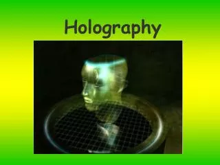
Chapter 5 Holography
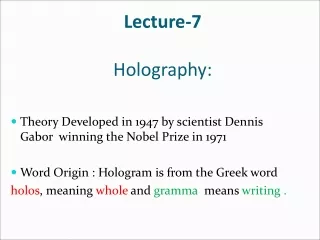
Chapter 5 Holography. Dennis Gabor in 1948 → the invention with the invention of laser → reached its full potential Leith and Upatnieks (1962) applied laser light to holography and introduced an important off-axis technique

Chapter 5 Holography
E N D
Presentation Transcript
Chapter 5 Holography Dennis Gabor in 1948 → the invention with the invention of laser → reached its full potential Leith and Upatnieks (1962) applied laser light to holography and introduced an important off-axis technique Gaber received Nobel Prize in 1971
Introductory Example The essence: Two steps of image formation a) Hologram: the object is transformed into a photographic record. b) Reconstruction: the hologram is transformed into the image. No lens is needed in either step!! A method of obtaining three-dimensional photographic images. These images are obtained without a lens, so the method is also called lensless photography. The records are called holograms.
3 attributes of light: • - intensity、color、direction • Not only the intensity distribution of reflected light is recorded but also the phase distribution. • - coherent reference beam interfere with the reflected waves. • Viewed from different angles, the object is also seen from different angles.
Introductory Example • Point object transparent zone plate: concentric diffraction rings with maxima and minima. • Two point object two overlapping zone plate • Complex object Object: An aggregate of points; Hologram: Multiplicity of rings; Reconstruction: an image of object
Hologram of a point source Construction of the hologram of a point source Any object can be represented as a collection of points Photographic plate • Photosensitive plate • Records interference pattern (linear response) • Emulsion has small grain structure () Reference wave - plane x z Object wave - spherical y
5.1 Producing the hologram • Hologram →the result of interference the signal→light diffracted by the object the reference→coherent background & directly reach • Photographic plate: only record intensities(amplitude) • Interference pattern(amplitude): contain the phase information
Conventional vs. Holographic photography • Conventional: • 2-d version of a 3-d scene • Photograph lacks depth perception or parallax • Film sensitive only to radiant energy • Phase relation (i.e. interference) are lost
Conventional vs. Holographic photography • Hologram: • Freezes the intricate wavefront of light that carries all the visual information of the scene • To view a hologram, the wavefront is reconstructed • View what we would have seen if present at the original scene through the window defined by the hologram • Provides depth perception and parallax
Questions: The photographic plate of hologram can only record the intensity of light. (1)True (2) False Which of the following statement is correct? (1)The hologram can directly record the phase and amplitude of the wave from object. (2)The hologram can only record the information of amplitude of object wave and reference wave. (3) The interference light intensity pattern from object wave and reference wave can be recorded by the hologram. (4)Reference wave is optional in the holographic setup.
5.1 Producing the hologram • Gaber’s approach: signal and reference beam are coaxial Object: a wire mesh, slender letters Light source: mercury arc Filter: isolate one of the Hg lines→ monochromatic light Pinhole stop: spatial coherency
Object wave Reference wave Real image Virtual image Direct wave Conjugate wave -z z z=0 Direct, object and conjugate waves
Hologram :Direct, object and conjugate waves • Direct wave: corresponds to zeroth order grating diffraction pattern • Object wave: gives virtual image of the object (reconstructs object wavefront) – first order diffraction • Conjugate wave: conjugate point, real image– first order diffraction • In general, we wish to view only the object wave – the other waves just confuse the issue
5.1 Producing the hologram • Leith and Upatneiks’ approach offset angle reference Possible to record 3D objects on hologram • Ensuring separation of the three waves on reconstruction • Possible to record 3D objects on hologram
Off-axisreconstruction: Direct, object and conjugate waves Use an off-axis system to record the hologram, ensuring separation of the three waves on reconstruction Reference wave Object wave Direct wave Conjugate wave Virtual image Real image
5.1 Producing the hologram • Practical setup Light source: laser Object: solid, 3D Photographic film: high resolution Hologram pattern: interference fringes Myriad of tiny domain —uniform gray —cannot be seen by naked eye containing a series of fringes of various lengths and spacing
Hologram pattern: Containing a series of fringes of various lengths and spacing.
Hologram –Reflection vs. Transmission • Transmissionhologram: reference and object waves traverse the film from the same side • Reflection hologram: reference and object waves traverse the emulsion from opposite sides View in Transmission View in reflection
5.2 Reconstruction (1) Hologram recorded intensity Light wave: vector A1— the signal, A2 —the reference, Each point on hologram: The asterisk* indicate the complex conjugate The transmittance function: T(x,y)
5.2 Reconstruction (2) Reconstruction process: A3 light is used to illuminate the hologram, the result pattern A4 is diffracted (modulated) by hologram. If A3 is equal, or proportional, to the reference amplitude A2 The image is a reconstruction of the object
5.2 Reconstruction A4 is the result of diffraction pattern by the hologram: s— distance between lines in hologram —the wavelength —diffraction angle For the 1st order: m=1
5.2 Reconstruction (3) Characters of holography a) No point to point relations between the object and the image • Photography: image point → object point (one to one) • Holography: a point on hologram → spreads to whole image a fragment of hologram → be reconstructed to whole image the size of the fragment → the resolution of the image b) 3D character • Light from both face & adjoining side → contribute to hologram • Different lines space in hologram → different 1th order of c) Both real and virtual imagecan be formed • Fraunhofer hologram – plane wave, same size • Fresnel hologram – recorded in divergent light real image↑, virtual image↓
5.2 Reconstruction (4) Practical consideration a) High resolution emulsion interference fringes must be resolved by the film ↑→ s↓ → resolution of film ↑, 100~200 line pairs/mm b) Coherent light source is needed C) Free from vibration during exposure • Typically long exposure times (~30s), so good stabilization is needed d) Always positive Hologram—negative → can be printed into positive(reversed black white) The reconstruction of negative → positive The reconstruction of positive → positive Reason: hologram --- the diffraction grating
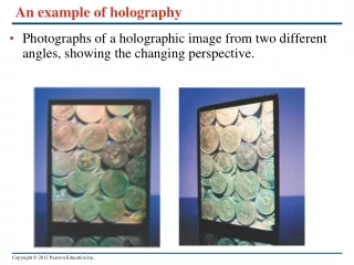
Example of a hologram • Horisontal and vertical parallax are clearly seen
Another example of a hologram • Depth is clearly seen
5.3 Application of Holography • Photography: two successive steps • Holography:two separated steps 1. Holographic Interferometry Measure technique very fast found application of holography to measure deformation and displacement of 3D objects. Hologram of the original object should be made before changes. Then object is deformed or moved. Now we can make the second exposure to verify changes. As the final result receive holographic image of interference pattern between original and distorted object.
Holographic interferometry • Vibration detection (time averaged)
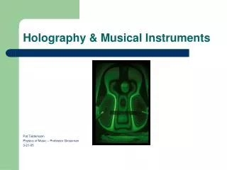
Holographic interferometry • applied on a guitar
Holographic interferometry • Interferogram of a turbine fan at 4460rpm recorded with a ”derotator” and a double-pulsed laser.
5.3 Application of Holography 2. Particle Size Determination
Holographic microscopy • A hologram can be recorded of a system and later studied in a microscope • Nice for studying systems in motion • Need to record the hologram during short period of time • => use pulsed laser
5.3 Application of Holography 3. Information Storage
Storing Data • We can convert binary data to an array of black-and-white pixels with a spatial light modulator (SLM). • We can store multiple “pages” of data in our holographic crystal. • We can then read back out our pages via the reference beam.
Surface storage • A commonality between recordable media is the fact that they store bits on a surface of the recording medium.
3D Storage - holograms • A hologram is a recording of an interference pattern made by the interaction of two beams of light. • Different image depending on the viewing angle • Using the volume of the storage medium as opposed to only its surface
5.3 Application of Holography 4. Acoustic Holography
5.3 Application of Holography 5.Holographic Optical Elements Holographic optical elements: Holographic grating • Cheap • Simple • Less random errors • Finer line separation • Drawback: Hard to produce eg triangular grooves
Other holographic opt. elements • Filter • Wavefront conversion • Image recognition • Barcode scanner
5.3 Application of Holography 6. Computer-generated Holograms A zone plate can easily be drawn using a suitable computer program. The printout, preferably made with a laser printer, is reduced in size and reconstructed; that results in a single point. But much more complex holograms can be synthesized as well. Their reconstructions produce surprisingly beautiful, three-dimensional images of objects, which, oddly enough, have never existed in the first place.
5.3 Application of Holography 7.Pattern Recognition
an image is the result of two successive Fourier transformations • Usually: • same time • same wave length • also: • not same time • --holography • not same time, not same wave length • --Buerger experiment
2 第一次变换 第二次变换 1 第一次变换:令X射线通过晶体得出劳厄斑 第二次变换:可见的相干光对频谱作变换得出晶格的像 Image magnification: 总的放大率可达 2.6×10⁷倍
STM( scanning tunneling microscope ): surface information This x-ray hologram shows the positions of cobalt atoms to within 0.1 Å
Stock Images are high quality reflection holograms. These holograms are on glass plates, and are not part of a signed, numbered edition. The following reflection holograms are 8" by 10", and are available for $750.00. These holograms come framed in a protective, black metal frame, ready for wall mounting. All of these holograms require a viewing light.
The Lilies reign in the quiet splendor and beauty of freshly-opened blossoms on a dew laden morning.
360 hologram Simple setup for making a 360 hologram