Download
1 / 15
150 likes | 272 Vues
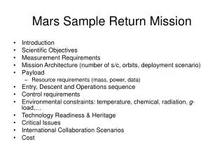
9 th International Planetary Probe Workshop Toulouse, France June 2012. Technology Development toward Mars Aeroflyby Sample Collection. K. Fujita*, T. Ozawa*, K. Okudaira†, T. Mikouchi‡, T. Suzuki*, H. Takayanagi*, Y. Tsuda*, N. Ogawa*, S. Tachibana‡, and T. Satoh*

E N D
9th International Planetary Probe Workshop Toulouse, France June 2012 Technology Development toward Mars AeroflybySample Collection K. Fujita*, T. Ozawa*, K. Okudaira†, T. Mikouchi‡, T. Suzuki*, H. Takayanagi*, Y. Tsuda*, N. Ogawa*, S. Tachibana‡, and T. Satoh* * Japan Aerospace Exploration Agency† University of Aizu‡ University of Tokyo
Background • Mars Exploration with Landers & Orbiters Synergy (MELOS) • Currently entertained in Japan (2020 launch) • Conglomerate mission where orbiters, landers, rovers, and/or airplanes are used for aeronomical, meteorological, and geoscientific researches as well as life search • To reveal why Mars is now in red – the fate of ancient water and carbon dioxide on the course of Martian history • Mission scenario • MELOS system is first inserted into primary orbit altogether • Entry systems are flown into Martian atmosphere using orbiter as a service module • Orbiter is maneuvered to final orbit for scientific operation → Great potential for a variety of probe vehicles incorporated into MELOS
Mars Aeroflyby Sample Collection (MASC) • Mission concept • Collection of Martian dust & gas samples during aeroflyby and return to Earth • Originally proposed by Leshin et al. as a candidate for Mars Scout mission • Scenario • Advantages • Valuable geological and aeronomical information on climatic vicissitude of Mars may be obtained at reasonable cost (compared to SR missions using a gigantic system) • Current dust models can be verified → better understanding of Martian climate • Sample return allows us more detailed analysis in Earth than in-situ analysis • Sample return allows us future reexamination of samples with improved instruments
Fundamental Design Parameters for MASC • Critical keys • Successful insertion to an orbit appropriate for earth return : precise GNC using lifting aeroshell is needed to cope with uncertainties in atmospheric density, aerodynamics of vehicle, & orbit/attitude determination • Minimization of total ∆V required for AOT, post-AOT maneuver, and earth return • Accessible lowest altitude < 40 km for sample collection • Minimization of TPS for aerodynamic heating
Fundamental Mission Design • Design criteria • Minimize total system mass (minimum dry mass of earth return subsystem may be almost determined by heritages of past systems) • Decrease propellant mass for earth return to minimize mass of orbiter subsystem • Increase apoapsis altitude of parking orbit to decrease ∆V for earth return • Decrease β for reduction of TPS mass • Increase β to enlarge ATO corridor
Aerodynamic Design • System requirements • L/D > 0.3 (up to 0.4 for α < 12) • β≈ 700 kg/m2 • Equipped with light-weight TPS • Equipped with RCS’s CFD(M=9.5) • Nose radius = 0.38 m • Half cone angle = 20⁰ • Base diameter = 1.63 m Wind tunnel (M=9.5)
TPS Design • Development of non-ablative light-weight TPS (NALT) • Non-ablative TPS is favorable for dust sampling during hypersonic flight • NALT consists of C/C skin, thermal insulator, and honeycomb structure • Conceptual design of MASC aeroshell • 1D TPS analysis along a flight trajectory (search for solutions by trial-&-error method) • Resulting in TPS area density of 9.0 kg/m2 at stagnation point, 7.5 kg/m2 in average, and total aeroshell mass of 133 kg 1D TPS analysis along flight trajectory
Design of GNC Subsystem • GNC subsystem configuration • Effective descent/ascent rate control by bank-angle modulation using RCS’s • Analytic predictor-corrector (APC) controller for primary GNC architecture • Lateral controller to minimize lateral deviation • Proportional–integral–derivative (PID) controller for yawing/pitching stabilization • Assessment of designed GNC controller robustness • Monte-Carlo simulation by taking into account uncertainties in atmospheric density, aerodynamics of vehicle, orbit determination, and guidance to entry I/F point • Results have shown sufficient robustness of designed GNC controller • Fuel used in bank-angle modulation is minimized by optimizing RCS’s operation
Dust Sampler Design • Approach • Retractable samplers (currently 2) are exposed for a few seconds • Samplers are located near aeroshell base to reduce heat transfer rate • Silica aerogel is used for capturing sample particles (like STARDUST) • Aerogel cells are transported to the reentry capsule inside MASC • Key issues • Damages inflicted on dust particles by high-temperature shock layer • Damages inflicted on aerogel exposed to high-temperature shock layer • Dust capturing capabilities of aerogel • damages inflicted on dust particles by impingement • capabilities of detecting & extracting dust samples stuck in the aerogel
Assessment of Sample Damages • Trajectory & heat transfer analysis of sample dust particles • Particles rush almost straightly across the shock layer and reach the aeroshell surface. • Particle temperature remains below the critical temperature since flight time < 5 μs. • Temperature raise can be reduced by optimizing position of the sample collector in relation to the flow around the forebody aeroshell. Trajectory & HT analysis Optimization of collectorlocation by means of CFD
Assessment of Aerogel Damages • Arcjet heating test campaign • 1st circular : aerogel surface was vitrified to the depth of several μm & charred materials were formed on the surface by oxidation of hydrophobizing agents • 2nd circular : an aerogel cell to shore up structural strength as well as to reduce heat transfer rate wassuccessfully demonstrated with non-hydrophobic aerogel • 3rd circular : non-silica aerogel specimens are tested to improve heat resistance 3rdtest campaign 2nd test campaign 1st test campaign Before • Carbon aerogel (CA) • CASA: CA/SA 2-layer aero-gel for higher heat-resistance After After
Assessment of Dust Capturing Capabilities • LGG dust capture tests (at Space Plasma Lab., ISAS) • Alumina/montmorillonite particles of 10-30μm in diameter were successfully captured by aerogel cells before/after arcjet-heating • Scan, extraction, & SEM/EDS analysis of samples has been successfully demonstrated • VdG dust capture tests (at HIT) • Argental particles of 1 μm in diameter were successfully captured by aerogel cells both before/after arcjet-heating. SEM/EDS Analysis (montmorillonite, 10 μm) VdG dust capture tests Particle surface is seen to somehow contaminated by melted aerogel. Afterimpingement Virgin particle (×1000)
System Configuration • Conceptual system design • Conducted based on the latest status of subsystem development, and on heritages of HAYABUSA sample return system • Further reduction of system mass may be realized by introducing new instruments
Development Plan (if applied to MELOS1) Phase A B C D MELOS1 E (~2022) D C Phase A B Demonstrators E (~2019) ~2024 MELOS Launch (2020) MELOS CDR (2018) MELOS PDR (2016) Demonstrator MDR (2012E) MELOS MDR (2013) ~2020 ~2015 ~2010 • Sampling demonstrator at Earth • AOT demonstrator at Mars ~2008 • Front-loading phase • Light-weight aeroshellequipped with TPS • GNC subsystem • Sample collector • Demonstrator design TRL 8 ~ 9 • Conceptualstudy • Verificationin laboratory Reentry system (HRV) Reusable system TRL 3 TRL 4 ~ 5 TRL 6 ~ 7
Conclusion • Mars Aeroflyby Sample Collection (MASC) using AOT technologies is proposed as a part of MELOS mission • Feasibility study of MASC has been conducted • The trajectory calculations have shown that a wide AOT corridor acceptable for the state-of-the-art GNC technologies in planetary explorations can be achieved by use of a lifting aeroshell with L/D > 0.3. • Preliminary R & D of the MASC subsystems are in progress • The integrated aeroshell with the TPS is designed to have a 7.5 kg/m2 area density • Robustness of developed GNC controller has been demonstrated • Overall examinations of dust sampling & analyzing techniques have been conducted • The dust particles are expected to reach the collector across the shock layer without fatal damages • Silica aerogel cell is found to capture dust samples of sub-μm in diameter, regardless of heat transfer from the high-temperature gases • MASC system is feasible with a minimum total mass of 600 kg • MASC is also applicable to other missions, or even solely