Communication Systems 14 th lecture
590 likes | 776 Vues
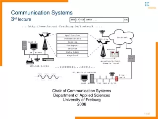
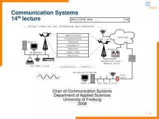
Communication Systems 14 th lecture. Chair of Communication Systems Department of Applied Sciences University of Freiburg 2008. 1 | 49. Communication Systems Last lecture – UMTS infrastructure. Please hand in the exercise sheet #6, next will be handed out in the next practical exercise

Communication Systems 14 th lecture
E N D
Presentation Transcript
Communication Systems14thlecture Chair of Communication Systems Department of Applied Sciences University of Freiburg 2008 1 | 49
Communication SystemsLast lecture – UMTS infrastructure Please hand in the exercise sheet #6, next will be handed out in the next practical exercise Sheet #7 is due for the 15th July (next lecture) Next two dates: 8th, 11th July – starting at 1:30pm (to catch up with the time of emitted courses in the beginning of the lecture) practical exercises in the computer center seminar room -114 (first day on IPv6 and SIP, second on QoS) please grab your older exercise sheets there to have a reference for exam preparation (we got quite a pile of papers by now :)) Type of exam still in discussion – request for a written version pending ... 2 | 49
Communication SystemsLast lecture – UMTS infrastructure Last session introduced UMTS Network architecture and interfaces, similarities and differences to GSM/GPRS User equipment and USIM Core network functionality and protocols (packet switched and circuit switched domain) UTRAN – UTMS radio network subsystem RNS, RNC, Node B Specific functions of the air interface (cell breathing, rake receiver) Network based and connection based functions Power control and hand-over 3 | 49
Communication SystemsLast lecture – UMTS – main network components 4 | 49
Communication SystemsLast lecture • UMTS Core Network (CN) migrates from 2G circuit switching to packet switching as introduced with GPRS to mobile networks • Thus many components and interfaces taken from GPRS, like the different GPRS support nodes (GSN) 5 | 49
Communication SystemsThis lecture – UMTS, Authentication, W-CDMA, encoding • Start with network authentication • UMTS physical layer: Frequency Division Duplex and WCDMA • Explanation of the code duplexing • Then switch over to other wireless technologies used for packet switched networks (IP) • Wireless LAN, widely deployed technology at consumers homes, unversities, companies... • Rather short overview on different WLAN standards • modulation, media access protocol MACA • 802.11 a/b/g standards and other standards • operation mode, components, services • First WLAN standards tried to introduce layer 2 security • Insecurity in WEP. 802.1x for AAA • 802.1i – Link layer encryption, TKIP and CCMP 6 | 49
Communication SystemsUMTS – the physical layer • After introduction of physical layer components (Node B) and principles (rake receiver and macro diversity) • Explanation of the Code Division Multiple Access • “Chips” instead of combined TDM, FDM • TDD and FDD frame structure • ... 7 | 53
Communication SystemsUMTS - WCDMA UTMS uses two methods for Terrestrial Radio Access: Frequency Division Duplex of two paired 5MHz bands Wideband CDMA Channels are divided via frequency distribution Time Division Duplex A single 5MHz frequency band Alternating WCDMA und TDMA as multiplexing method4 8 | 49
Communication SystemsUMTS - WCDMA Code Division Multiple Access (CDMA) has some advantages over the GSM methods FDMA, TDMA, CDMA compared in their principles 9 | 49
Communication SystemsUMTS - WCDMA Code Division Multiple Access (CDMA) has some advantages over the GSM (FDMA, TDMA) methods More efficieny in frequncy band usage Higher data rates (on demand) Longer standby and operation for mobile equipment (less transmit power needs to be generated) Greater ranges between mobile phones and Node Bs (for voice) Flexible adjustment of radio traffic onto the demands – voice gaps of active participants could be used for other traffic channels and users Disruption of signal not neccessarily disrupts a session Switching from physical to mathematical methods 4 10 | 49
Communication SystemsUMTS - WCDMA WCDMA: Codemultiplex vs. Frequency / time multiplex Multiple signale on just one frequency Demultiplexing independent of channel bundling Per participant a binary channalization code is used 11 | 49
Communication SystemsUMTS - WCDMA Channalization code is used for and decoding and is spread with a vector of a length of e.g. 128Bit No bits but so called chips are used The Codes have to be orthogonal Example for a chipping length of 6 User code A: (0,1,0,0,1,1) User code B: (1,1,0,1,0,1) 4 12 | 49
Communication SystemsUMTS – WCDMA – chip computation User A sends Ad=1 Key Ak = (0,1,0,0,1,1) Non return to zero computed of Ad & Ak Chips sent: As = Ad * Ak Results in (-1,+1,-1,-1,+1,+1) 4 User B sends Bd=1 Key Bk = (0,1,0,0,1,1) Non return to zero computed of Bd & Bk Chips sent: Bs = Bd * Bk Results in (-1,+1,-1,-1,+1,+1) 13 | 49
Communication SystemsUMTS – WCDMA, OVSF code tree Addition of all chips: As + Bs = (-1,+1,-1,-1,+1,+1) + (-1,-1,+1,-1,+1,-1) = (-2, 0, 0,-2,+2, 0) Decoding check all received chips with Ak / Bk (NRZ) Ae = (-2, 0, 0,-2,+2, 0) * Ak = 2 + 0 + 0 + 2 + 2 + 0 = 6 Be = (-2, 0, 0,-2,+2, 0) * Bk = -2 + 0 + 0 - 2 – 2 + 0 = -6 Result should be a 6 or -6 which equals to a „1“ set bit or „0“ WCDMA uses a fixed chiprate of 3,84 MChips/s Important is the variable spreading factor Different code lengthes are used for up and downlinks Spreading factor of 512 in Downlink, thus every Node B uses the complete code tree 4 14 | 49
Communication SystemsUMTS – WCDMA, OVSF code tree Maximum spreading factor of 256 used in uplink Scrambling for the complete code tree needed 4 15 | 49
Communication SystemsUMTS – WCDMA, OVSF code tree If code on a node in the code tree is assigned, the subsequent codes could not be assigned to other (not orthogonal then) Scrambling of signals is the following Multiplication of a code sequence of 1 and -1 (NRZ) into the signal Assigned identity via the scrambling code is nearly 100% orthogonal Advantages time shifited sending (Position within a cell) Deliniation toward bordering cells Equal spectral distribution 4 16 | 49
Communication SystemsUMTS – WCDMA Chips instead of bits has some advantages and disadvantages Negative is that you have to send e.g. 128 times more data and reduces the data rate extremely Positive is to increase the transmission qualitty More codes means more orthogonals thus 128 users on one Node B WCDMA allows a reduced signal/noise ratio, thus Reduced transmit power needed, processing Gain achieved Tradeoff: High spreading factor (SF) allows high processing gain but low data rate, low Sfgets low processing gain but high data rates 17 | 49
Communication SystemsUMTS – security and authentication • Security in GSM is weak by our todays standards, mostly broken and only one way (client-to-network auth) • Authentication in UMTS • Base is a common secret key K, which is only known by the USIM (User Services Identity Module) in the UE and by the HLR/AuC of the provider • The VLR or SGSN which should authenticate the user requests from the HLR/AuC 1..n AV(Auth Vectors) • Each AV is a 5-tupel consisting of • RAND (random challenge) and XRES (expected response) for the user authentication • CK (cipher key) for protection of confidentiality, IK (integrity key) for protection of integrity, AUTN (auth token) for network authentication 18 | 53
Communication SystemsUMTS – security and authentication 19 | 53
Communication SystemsUMTS – security and authentication • RAND and AUTN are sent to the UE/USIM, which checks AUTN and computes the response RES to the challenge RAND • RES is sent to the VLR/SGSN which compares it to XRES • Integrity and confidentiality • By request of MSC/VLR or SGSN the communication can be encrypted with CK or IK between UE and RNC • Encryption takes place on the RLC layer and prevents forgery of data and encryption 20 | 53
Communication SystemsUMTS – security and authentication • Functions for authentication and key agreement (AKA) • f1: computation of MAC (Message Auth. Code) • f2: computation of MAC, probably shortened • f3, f4, f5: computation of a key from a random number • XOR, || concatenation • Generation of AV (within HLR/AuC) • Generation of random Sequence Number (SEQ, once at the beginning) • Generation of random challenge RAND (per AV) • AMF (Authentication Key Management Field) to distinguish several different algorithms 21 | 53
Communication SystemsUMTS – security and authentication • Computation of the several values (within HLR/AuC) • MAC=f1 (SQN || RAND || AMF) • XRES=f2 (RAND) • CK=f3 (RAND) • IK=f4 (RAND) • AK=f5 (RAND) , anonymity key to anonymize SQN • AUTN= ((SQN AK) || AMF || MAC) • AV= (RAND || XRES || CK || IK || AUTN) 22 | 53
Communication SystemsUMTS – security and authentication • Computation of the several values (within USIM) • Reception of RAND and AUTN from VLR or SGSN • AK=f5 (RAND) • SQN=(SQN AK) AK • XMAC=f1 (SQN || RAND || AMF) (eXpected MAC) • Comparison of XMAC and MAC (from AUTN) • If this procedure fails the authentication of network does not succeed and the UE sees the cell as forbidden • Check if sequence number is from the expected range • RES=f2 (RAND) 23 | 53
Communication SystemsUMTS – security and authentication • Computation of the several values (within USIM, cont.) • Send response to VLR or SGSN with RES • CK=f3 (RAND • IK=f4 (RAND) • IK, CK used for RLC encryption • Operation within VLR or SGSN • Reception of RES from the USIM • Comparison of RES with XRES (eXpected RES, from AV sent by HLR/AuC) • If not equal user authentication failed 24 | 53
Communication SystemsUMTS – end of mobile telephony part Topic switch: stay in the mobile network domain but switch from mobile telephony part return to infrastructures mainly developed for Internet protocol / packet switched networks During the next periods we will see a move of both networks IP and telephony into a more merged on – principles and ideas o the other one could be found in each network (IP in UTMS infrastucture, ideas of telephony in VoIP services) Have a look on some other wireless technologies for data transmission Same idea: The user should be able to move around but keep a network connection Increasingly possible with the development of the broad range of mobile devices and technology 25 | 49
Communication SystemsWireless LAN technology - introduction Ethernet defines LAN standards for relatively short distances over coaxial cable, twisted pair copper wire or fiber optics ADSL extends the data rates achievable on customers telephone connections over (old) two wire copper But: Cable may not present everywhere Cabling may be very expensive (crossing streets or rivers) or impossible (historical buildings, prohibition of owners, ...) Desire for ad-hoc LANs Wish for cable-less offices Changing number of connections needed in an office (desktop pc, laptop, other devices ...) 26 | 49
Communication Systemswireless technology - introduction Problems to be solved which differences exist in comparison to wired LAN which data rates are achievable security issues (wired network connectors are not easily misusable if office is locked, but wireless LANs may cross office/building boundaries easily) ranges of different wireless technologies how to organize network access of multiple stations (especially if they are not “see” each other) 27 | 49
Communication Systemswireless technology - introduction 28 | 49
Communication Systemswireless LAN - history • 1997 the IEEE approved 802.11, which specified the characteristics of devices with a signal rate of 1 and 2 Mb/s. • The standard specifies the MAC and the physical layers for transmissions in the 2.4 GHz band. • 1999, the IEEE ratified a new amendment, called IEEE 802.11b, which works at additional signal rates of 5.5 and 11 Mb/s. • Hereinafter, to the IEEE 802.11 standards as Wi-Fi(Wireless-Fidelity), certifying device interoperability. • 1999, the IEEE approved the specifications of 802.11a, which uses the 5 Ghz band. The signal rates are 6, 9, 12, 18, 24, 36, 48 and 54 Mb/s. • In 2003, the IEEE approved 802.11g as a further evolution of the 802.11 standard. • 802.11g provides the same performance as 802.11a, while working in the 2.4 GHz band. Compatible with 802.11b devices. 29 | 49
Communication Systemswireless LAN – basics Moving electrons send out waves, which spread in free space, vacuum Frequency(f): number of oscillations per second measured in Hertz (Hz) Wavelength (λ) is the distance between two maxima Speed of wave spreading in vacuum c = 3 108 m/s = 30 cm/ns 30 | 49
Communication Systemswireless LAN – modulation FHSS different protocols available frequency hopping spread spectrum (FHSS) 79 channels of 1MHz bandwidth within the 2.4GHz band a pseudo random generator initiates each hop the minimum hopping distance is 6MHz the maximum of 26 participants could share the medium without bandwidth restriction (but max. bandwidth is 2Mbits) if collision occurs the data is simply transferred again low power consumption -> used for Bluetooth 31 | 49
Communication Systemswireless LAN – modulation DSSS different protocols available direct sequence spread spectrum (DSSS) bundles the 79 channels of 1MHz into broader channels of 5MHz a minimum distance of 5 channels should be adhered within modulation the signal is spreaded the channels may overlap, so the maximum of three independent services sets are possible extension is high rate DSSS b standard uses HR-DSSS 32 | 49
Communication Systemswireless LAN – modulation OFDM different protocols available orthogonal frequency (OFDM) multi carrier modulation technology 52 frequency bands, for of them for synchronization small bands are less susceptible for disturbance and noise avoiding of the use of directly neighbored frequencies used for the g and a,j,h standards 33 | 49
wireless LANs need more complex media access protocols than wired LANs restricted range of signals makes it more difficult to have a global signal detection move from cell to cell should be possible (roaming), so a mobile station could communicate during transit OSI layer 2 is split up once more a special MAC sublayering is introduced Communication Systemswireless LAN – media acess 34 | 49
this layer handles cyclic redundancy check (CRC) fragmentation (no to be confused with IP fragmentation) authentication WEP encryption auto roaming with the latter a unified network over more than one station becomes possible other layer is physical layer convergence protocol e.g. defines modulation: FHSS, DSSS, HR-DSSS, OFDM, IrDA Communication Systemswireless LAN – media access 35 | 49
would think of CSMA/CD first (carrier sense multiple access with collision detection seems to solve our problem) but see picture below restricted range of signals 1 talks to 2 3 thinks medium is free for use - “hidden station problem” Communication Systemswireless LAN – access protocols 36 | 49
or inefficient use of given bandwidth if 1 transfers to 2 (or vice versa), 3 could think that medium is blocked and does not transfer to 4 give away of bandwidth - “exposed station problem” therefore new access protocol: MACA (multiple access with collision avoidance) before data is transferred send out a short test sequence: RTS (ready to send) – sender asks if medium is available for transferring data packets destination stations of data exchanges answers with CTS (clear to send) all stations which received RTS have to remain silent for a given time period Communication Systemswireless LAN – access protocols: MACA 37 | 49
There is an optimization of this protocol: MACA (W), W for wireless Other protocol (but rather different) using collision avoidance – TokenRing, FDDI Communication Systemswireless LAN – access protocols: MACA 38 | 49
802.11 is a member of the IEEE 802 family, including several standards The standards define transmission protocols and brutto bandwidth Communication Systemswireless LAN standards – 802.11 overview 39 | 49
Communication Systemswireless LAN standards – 802.11 overview • b – available several years, 11Mbit/s, 2.4GHz, 13 channels in Germany • but only 3 non overlapping channels • utilize the free 2.4GHz band → it is rather packed, no exclusive use • no guarantees (if you mess with other bands someone of the RegTP will stop you, only excess of output power is prohibited) • special protocol implementations needed to cope with noise, fading, ... • not standardized 22Mbits in 2.4GHz band of several vendors (sometimes called b+, channel bundling) • g – defined 2003, 54Mbits, 2.4GHz, OFDM • most of the hardware sold at the moment confirms to this standard • backward compatible to “b”, but then more overhead compared to “clean” g standard networks (preamble an initialization sequence must be handled within b standard) 40 | 49
a – 54Mbit/s standard for the 5GHz band, 12 non-overlapping channels, OFDM (orthogonal frequency division multiplexing), restricted output power introduction of transmit power control (TPC) and dynamic frequency selection (DFC) DFS should reduce the transmission power so it is sufficient for a given connection but does not spread farther than needed it checks if the used frequency is free and sufficient, if not tries to switch over to another frequency with DFC band is reserved for WLAN only range is more restricted than with 802.11b bandwidth is increased up to 54Mbit/s Communication Systemswireless LAN standards – 802.11 overview 41 | 49
h – 54Mbit/s standard extension for Europe within the 5GHz band, defined standards for indoor and outdoor use j – extension of a for Japan the usable bandwidth for the several standards is much lower than the maximum one in b standard networks under optimal environment up to nearly 6Mbit/s of higher level protocol data speed is possible in g standard you might achieve up to 30Mbit/s the remaining capacity is consumed for WLAN preambles, protocol headers, coordination Communication Systemswireless LAN standards – 802.11 overview 42 | 49
More standards defining several other aspects of WLANs c – wireless bridging d – world mode (combined definitions for different countries) e – quality of service (QoS on layer 2), packet priorization for real time multimedia and Voice over IP f – general definition of roaming between access points (of different vendors) i – authentication and encryption k – better measurement of WLAN parameters for increase of signal quality, dense networks and location based services (LBS) m – summarization of extensions to the protocol n – extension of bandwidth up to 108-320Mbit/s Communication Systemswireless LAN standards – 802.11 overview 43 | 49
Wi-Fi (wireless fidelity) certificate of interoperability of wireless devices each device is marked with a 48bit MAC address as known from the ethernet world allocation of frequency spectrum 802.11a,j,h: 8 20-MHz channels in the frequency band from 5,15GHz up to 5,35GHz 802.11b and g: 14 channels in the 2,4GHz band distribution of channels different in different countries, not all channels available in every country with a tight woven network of access points a clever setup of channels is needed Communication Systemswireless LAN standards – 802.11 overview 44 | 49
more than one access point in a given area possible if channels are at least by a number three away from each other WLAN of 802.11 offer several operation modes Ad-Hoc (peer-to-peer mode, no access point) Managed (point-to-point connection from mobile device to access point) Access Point (flow control between base station and switch or more than one base station – for roaming etc.) Communication Systemswireless LAN – 802.11 operation mode 45 | 49
Communication Systemswireless LAN – 802.11 components and services • In managed mode 802.11 provides nine Services: • Distribution • Integration • Association • Reassociation • Disassociation • Authentication • Deauthentication • Confidentiality • MSDU delivery • Transmit Power Control (TPC) • Dynamic Frequency Selection (DFS) 46 | 49
Communication Systemswireless LAN – 802.11 Frame format • Protocol version: At present, protocol number 0 • Type and subtype: identify the type of frame • ToDS and FromDS bits: whether a frame is destined for distribution system • Retry bit: any retransmitted frames set this bit to 1 • Power management bit: indicates whether the sender will be in a powersaving mode after the completion of the current atomic frame exchange. 47 | 49
Communication Systemswireless LAN – 802.11 (in)security • AAA: Authentication, Authorization, Accounting • 802.11 specification defines Open and Shared Key authentication. • Open authentication is a null authentication algorithm. The AP grants any request for authentication. • Shared Key authentication requires that the client station and the AP have WEP enabled and have matching WEP keys • 802.11 specification defines WEP to provide data encryption. • WEP is based on the RC4 symmetric stream cipher. • Matching WEP keys must be statically configured on both client and infrastructure devices. • You can define up to four keys on a device, but you can use only one at a time for encrypting outbound frames. 48 | 49
problems WLANs are very open connection secured through WEP (wired equivalent security), works with 64 and 128Bit keys but: clear text initialization vector (24Bit), which precedes every packet for that reason WEP key is only of 40 or 104Bit WEP was cracked four years ago The 802.11 specification does not specify key-management mechanisms. WEP is defined to support only static, preshared keys. other solutions ... Communication Systemswireless LAN – 802.11 (in)security 49 | 49
Communication Systems802.1X - Network Port Authentication • Port-Based Network Access Control • Provides a framework for user authentication and key management over any LANs, including wireless LAN. • The "port" in 802.1X on wireless LAN is an association between a wireless device and its access point. • Authenticate users rather than machines. • Authentication is at the link layer • It is an IEEE adaptation of the IETF's Extensible Authentication Protocol (EAP). • Can update keys dynamically periodically 50 | 49