Download
1 / 70
730 likes | 1.05k Vues
Chapter 1 Fundamental concepts of computer networks. Chapter 1 Fundamental concepts of computer networks. Lecture 1. 1-1 DATA COMMUNICATIONS.

E N D
Chapter 1 Fundamental concepts of computer networks.
Chapter 1 Fundamental concepts of computer networks. Lecture 1
1-1 DATA COMMUNICATIONS The term telecommunication means communication at a distance. The word data refers to information presented in whatever form is agreed upon by the parties creating and using the data. Data communications are the exchange of data between two devices via some form of transmission medium such as a wire cable or wireless. Delivery → Correct destination Accuracy → Accurate data Timelines → Real-time transmission Jitter → Uneven delay
Topics discussed in this section: Components Data RepresentationData Flow Components Figure 1.1 Five components of data communication 5 1 2 3 4
Data Representation Text Numbers Images Audio Video • Data flow • Simplex • Half-duplex • Full-duplex
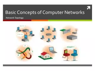
1-2 NETWORKS A network is a set of devices (nodes) connected by communication links. A node can be a computer, printer, or any other device capable of sending and/or receiving data generated by other nodes on the network. Topics discussed in this section: Distributed Processing Network Criteria (performance, reliability, and security)Physical Structures ( type of connections and topologies)Network Models Categories of Networks ( LAN, MAN and WAN)Interconnection of Networks: Internet
Types of connections • Point to point • A dedicated link is provided between two devices • Multipoint • More than two specific devices share a single link
Physical Topology Tree
MESH Topology • Every device has a dedicated point-to-point link to every other devices • Dedicated • Link carries traffic only between the two devices it connects • A fully connected mesh network has n(n-1)/2 physical channels to link n devices • Every device on the network must have n-1 input/output (I/O) ports • Advantage • Less traffic, robust, secure, easy to maintain • Disadvantage • Need more resource (cable and ports), expensive n(n-1)/2 physical duplex links
STAR Topology • Each device has a dedicated point-to-point link only to a central controller, usually called a hub. • No direct traffic and link between devices • Advantages • Less expensive • Easy to install and reconfigure • Robustness • Disadvantage • Single point of failure
BUS Topology • A multipoint topology • All devices are linked through a backbone cable • Nodes are connected to the bus cable by drop lines and taps. • Drop line • A connection running between the device and the main cable • Tap • A connector that either splices into the main cable or punctures the sheathing of a cable to create a contact with the metallic core • Advantage: • Ease of installation • Disadvantages: • Difficult reconnection and fault isolation • Broken or fault of the bus cable stops all transmission
RING Topology • Each device is dedicated point-to-point connection only with the two devices on either side of it • A signal is passed along the ring in the direction, from device to device, until it reaches its destination • Each device in the ring incorporates a repeater • Advantages • Relatively easy to install and reconfigure • Fault isolation is simplified • Disadvantage • Unidirectional traffic
Tree Topology Tree topologies integrate multiple topologies together • Advantages: • Point-to-point wiring for individual segments. • Supported by several hardware and software venders. • Disadvantages: • Overall length of each segment is limited by the type of cabling used. • If the backbone line breaks, the entire segment goes down. • More difficult to configure and wire than other topologies. Example: Tree topology integrates multiple star topologies together onto a bus
Categories of Networks Local Area Network (LAN) Wireless Local Area Network (WLAN) Metropolitan Area Network (MAN) Wide Area Network (WAN) An isolated LAN connecting 12 computers to a hub in a closet
Interconnection of Networks: internet A heterogeneous network made of four WANs and two LANs
1-3 THE INTERNET The Internet has changed many aspects of our daily lives. It has affected the way we do business as well as the way we spend our leisure time. The Internet is a communication system that has brought a wealth of information to our fingertips and organized it for our use. Topics discussed in this section: A BriefHistory → ARPANET • 1967 ACM • 1969 UCLA, UCSB, SRI, UoU • 1972 TCP The Internet Today (ISPs)
1-4 PROTOCOLS AND STANDARDS protocols and standards. Protocol is synonymous with rule. Standards are agreed-upon rules. Topics discussed in this section: Protocols Standards Standards Organizations Internet Standards
PROTOCOLS AND STANDARDS Protocols • Syntax → format of the data • Semantics → meaning of each section • Timing → when data should be sent and how fast. • Standards • De facto → by fact (not approved as a standard) • De jure → by Law (approved)
PROTOCOLS AND STANDARDS Standards Organizations • International Organization for Standardization (ISO) • International Telecommunication Union - Telecommunication Standards (ITU-T) • American National Standards Institute (ANSI) • Institute of Electrical and Electronics Engineers (IEEE) • Electronic Industries Association (EIA)
Network Models Lecture 2 OSI Model
1-5 LAYERED TASKS • A network model is a layered architecture • Task broken into subtasks • Implemented separately in layers in stack • Functions need in both systems • Peer layers communicate • Protocol: • A set of rules that governs data communication • It represents an agreement between the communicating devices
Tasks involved in sending a letter Topics discussed in this section: Sender, Receiver, and CarrierHierarchy (services)
1-5.1 THE OSI MODEL Established in 1947, the International Standards Organization (ISO) is a multinational body dedicated to worldwide agreement on international standards. An ISO is the Open Systems Interconnection (OSI) model is the standard that covers all aspects of network communications from ISO. It was first introduced in the late 1970s.
ISO is the organization.OSI is the model. Topics discussed in this section: Layered ArchitecturePeer-to-Peer Processes Encapsulation
Layered Architecture Seven layers of the OSI model Receiver Sender
Layered Architecture • A layered model • Each layer performs a subset of the required communication functions • Each layer relies on the next lower layer to perform more primitive functions • Each layer provides services to the next higher layer • Changes in one layer should not require changes in other layers • The processes on each machine at a given layer are called peer-to-peer process
PEER – TO – PEER PROCESS • Communication must move downward through the layers on the sending device, over the communication channel, and upward to the receiving device • Each layer in the sending device adds its own information to the message it receives from the layer just above it and passes the whole package to the layer just below it • At the receiving device, the message is unwrapped layer by layer, with each process receiving and removing the data meant for it
PEER – TO – PEER PROCESS • The passing of the data and network information down through the layers of the sending device and backup through the layers of the receiving device is made possible by interfacebetween each pair of adjacent layers • Interface defines what information and services a layer must provide for the layer above it.
LAYERS IN THE OSI MODEL Topics discussed in this section: Physical Layer Data Link Layer Network Layer Transport Layer Session Layer Presentation Layer Application Layer
Physical Layer The physical layer is responsible for movements of individual bits from one hop (node) to the next. • Function • Physical characteristics of interfaces and media • Representation of bits • Data rate • Synchronization of bits • Line configuration (point-to-point or multipoint) • Physical topology (mesh, star, ring or bus) • Transmission mode ( simplex, half-duplex or duplex)
Data Link Layer The data link layer is responsible for moving frames from one hop (node) to the next. • Function • Framing • Physical addressing • Flow control • Error control • Access control
Example 1 In following Figure a node with physical address 10 sends a frame to a node with physical address 87. The two nodes are connected by a link. At the data link level this frame contains physical addresses in the header. These are the only addresses needed. The rest of the header contains other information needed at this level. The trailer usually contains extra bits needed for error detection
Network Layer The network layer is responsible for the delivery of individual packets from the source host to the destination host. • Source-to-destination delivery • Responsible from the delivery of packets from the original source to the final destination • Functions • Logical addressing • routing
Example 2 We want to send data from a node with network address A and physical address 10, located on one LAN, to a node with a network address P and physical address 95, located on another LAN. Because the two devices are located on different networks, we cannot use physical addresses only; the physical addresses only have local influence. What we need here are universal addresses that can pass through the LAN boundaries. The network (logical) addresses have this characteristic.
Transport Layer The transport layer is responsible for the delivery of a message from one process to another. • Process-to- process delivery • Functions • Port addressing • Segmentation and reassembly • Connection control ( Connection-oriented or connection-less) • Flow control • Error control
Transport layer Segmentation and reassembly
Example 3 Data coming from the upper layers have port addresses j and k (j is the address of the sending process, and k is the address of the receiving process). Since the data size is larger than the network layer can handle, the data are split into two packets, each packet retaining the port addresses (j and k). Then in the network layer, network addresses (A and P) are added to each packet.
Session Layer The session layer is responsible for dialog control and synchronization. • It establishes, maintains and synchronize the interaction between communicating system • Function • Dialog control • Synchronization (checkpoints)
Session layer Synchronization