Download
1 / 1
10 likes | 180 Vues
35 mm. 18 mm. 28.8 mm. 124.8 mm. 20 mV. 20 ns. 40 ns. ΔT =1µs.

E N D
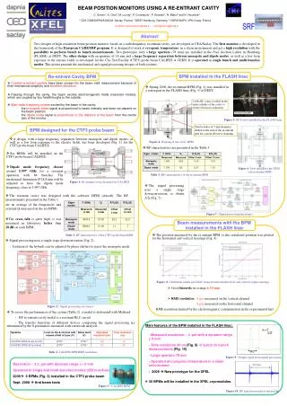
35 mm 18 mm 28.8 mm 124.8 mm 20 mV 20 ns 40 ns ΔT =1µs BEAM POSITION MONITORS USING A RE-ENTRANT CAVITY C. Simon1, S. Chel1, M. Luong1, P. Contrepois1, P. Girardot1, N. Baboi2 and N. Rouvière31 CEA DSM/DAPNIA/SACM, Saclay, France, 2 DESY Hamburg, Germany, 3 CNRS IN2P3 –IPN Orsay, FranceContact: claire.simon@cea.fr - michel.luong@cea.fr Abstract Two designs of high resolution beam position monitor, based on a radiofrequency re-entrant cavity, are developed at CEA/Saclay. The first monitor is developed in the framework of the European CARE/SRF program. It is designed to work at cryogenic temperature, in a clean environment and get a high resolution with the possibility to perform bunch to bunch measurements. Two prototypes with a large aperture (78 mm) are installed in the Free electron LASer in Hamburg (FLASH), at DESY. The other design with an aperture of 18 mm and a large frequency separation between monopole and dipole modes, as well as a low loop exposure to the electric fields is developed for the Clic Test Facility (CTF3) probe beam CALIFES at CERN. It is operated in single bunch and multi-bunches modes. This poster presents the mechanical and signal processing designs of both systems. BPM installed in the FLASH linac Re-entrant Cavity BPM • Coaxial re-entrant cavities have been chosen for the beam orbit measurement because of their mechanical simplicity and excellent resolution. • Passing through the cavity, the beam excites electromagnetic fields (resonant modes), which are coupled by four feedthroughs to the outside. • Main radio-frequency modes excited by the beam in the cavity: • the monopole mode signal is proportional to beam intensity and does not depend on the beam position • the dipole mode signal is proportional to the distance of the beam from the centre axis of the monitor. • Spring 2006, the re-entrant BPM (Fig. 4) was installed in a warm part in the FLASH linac (Fig. 5) at DESY. Cu-Be RF contact welded in the inner cylinder of the cavity to ensure electrical conduction. Figure 5: RF Cavity installed in the FLASH linac Twelve holes of 5 mm diameter drilled at the end of the re-entrant part for a more effective cleaning. BPM designed for the CTF3 probe beam • A design, with a large frequency separation between monopole and dipole modes, as well as a low loop exposure to the electric fields, has been developed (Fig. 1) for the CTF3 probe beam CALIFES. Figure 4: Drawing of the cavity BPM • RF characteristics are presented in the Table 3. • Six BPMs will be installed on the CTF3 probe beam CALIFES. • Dipole mode frequencychosen around 5.997 GHz for a resonant operation with 64 bunches. The mechanical dimension Ø 28.8 mm will be adjusted to have the dipole mode frequency close to 5.997 GHz. Figure 6 :New design for the XFEL cold re-entrant BPM Table 3: RF characteristics of the re-entrant BPM Figure 1: Re-entrant cavity designed for CALIFES • The signal processing uses a single stage downconversion to obtain Δ/Σ (Fig. 7) . • The resonant cavity was designed with the software HFSS (Ansoft). The RF measurements presented in the Table 1 are an average of the frequencies and external Q measured on the six BPMs . • The cross_talk is quite high, it was measured in laboratory better than 28 dB on each BPM. Figure 7 : Signal processing electronics Beam measurements with the BPM installed in the FLASH linac Table 1: RF characteristics of the CTF3 probe beam BPM • The position measured by the re-entrant BPM vs the calculated position was plotted for the horizontal and vertical steerings (Fig. 8). • Signal processing uses a single stage downconversion (Fig. 2). - Isolation of the hybrids can be adjusted by phase shifters to reject the monopole mode Figure 8.Calibration results in LINAC frame from horizontal (left) and vertical (right) steerings • Good linearity in a range 15 mm • RMS resolution : 4 µm measured on the vertical channel 8 µm measured on the horizontal channel Figure 2 : Signal processing electronics RMS resolution limited by the electromagnetic contamination in the experimental hall • To assess the performances of the system (Table 2), a model is elaborated with Mathcad. - RF re-entrant cavity model is a resonant RLC circuit - The transfer functions of different devices composing the signal processing are determined by the S parameters measured with a network analyzer. Main features of the BPM installed in the FLASH linac: - Measured resolution ~ 4 µm with a dynamic range 5 mm - Time resolution 40 ns (Fig. 9) bunch to bunch measurements (Fig. 10) - Large aperture 78 mm - Operated at cryogenic temperature in a clean environment - 2008 New prototype for the XFEL Table 2. CALIFES BPM RMS resolution Figure 9 : Output signal from signal processing Resolution ~ 3.2 µm with dynamic range +/- 5 mm Operated in single and multi-bunches modes (226 bunches) 2008 6 BPMs (Fig. 3) installed in the CTF3 probe beam Sept. 2008 first beam tests • 30 BPMs will be installed in the XFEL cryomodules. Figure 3 : CALIFES BPM Figure 10: RF signal measured at one pickup


