Digital Electronics Minimization using Karnaugh Map by Dr. M.Manikandan Associate Professor
550 likes | 757 Vues
Digital Electronics Minimization using Karnaugh Map by Dr. M.Manikandan Associate Professor Dept of Electronics Engineering Anna University. Overview. K-maps: an alternate approach to representing Boolean functions K-map representation can be used to minimize Boolean functions

Digital Electronics Minimization using Karnaugh Map by Dr. M.Manikandan Associate Professor
E N D
Presentation Transcript
Digital ElectronicsMinimization using Karnaugh MapbyDr. M.Manikandan Associate Professor Dept of Electronics Engineering Anna University
Overview • K-maps: an alternate approach to representing Boolean functions • K-map representation can be used to minimize Boolean functions • Easy conversion from truth table to K-map to minimized SOP representation. • Simple rules (steps) used to perform minimization • Leads to minimized SOP representation. • Much faster and more more efficient than previous minimization techniques with Boolean algebra.
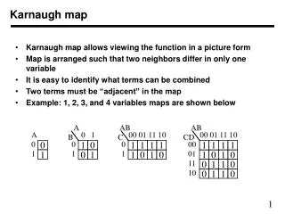
y 0 1 x x’y’ x’y 0 y x y F 0 0 1 0 1 1 1 0 0 1 1 0 1 x xy’ xy 0 1 x 1 1 0 1 0 0 Karnaugh maps • Alternate way of representing Boolean function • All rows of truth table represented with a square • Each square represents a minterm • Easy to convert between truth table, K-map, and SOP • Unoptimized form: number of 1’s in K-map equals number of minterms (products) in SOP • Optimized form: reduced number of minterms F = Σ(m0,m1) = x’y + x’y’ y
B 0 1 A 0 0 1 F=AB+A’B 1 1 0 BC 00 01 11 10 A 0 0 1 0 1 1 1 1 1 1 Karnaugh Maps • A Karnaugh map is a graphical tool for assisting in the general simplification procedure. • Two variable maps. B 0 1 A 0 0 1 F=AB+AB+AB 1 1 1 A B F C • Three variable maps. 0 0 0 0 0 0 1 1 0 1 0 1 0 1 1 0 1 0 0 1 1 0 1 1 1 1 0 1 1 1 1 1 + F=AB’C’+ABC+ABC +ABC + A’B’C + A’BC’
Rules for K-Maps • We can reduce functions by circling 1’s in the K-map • Each circle represents minterm reduction • Following circling, we can deduce minimized and-or form. Rules to consider • Every cell containing a 1 must be included at least once. • The largest possible “power of 2 rectangle” must be enclosed. • The 1’s must be enclosed in the smallest possible number of rectangles. Example
B B 0 1 0 1 A A 0 0 1 0 0 1 F=AB+A’B 1 1 0 1 1 1 BC 00 01 11 10 A 0 0 1 0 1 1 1 1 1 1 Karnaugh Maps • A Karnaugh map is a graphical tool for assisting in the general simplification procedure. • Two variable maps. F=AB+AB+AB F=A+B • Three variable maps. F=A+BC+BC F=AB’C’+ABC+ABC +ABC + A’B’C + A’BC’
G(A,B,C) = A A A 1 0 0 0 0 0 0 0 0 1 1 1 1 1 1 1 F(A,B,C) = m(0,4,5,7) C C = AC + B’C’ A AB B B 11 10 00 01 C 0 1 C B Karnaugh maps • Numbering scheme based on Gray–code • e.g., 00, 01, 11, 10 • Only a single bit changes in code for adjacent map cells • This is necessary to observe the variable transitions
More Karnaugh Map Examples • Examples a a 0 1 b 0 1 0 0 1 b 0 1 1 1 0 1 1 0 0 f = a g = b' ab ab c 00 01 11 10 c 00 01 11 10 0 0 0 1 0 0 0 1 1 0 0 1 1 1 1 0 0 1 1 1 cout = ab + bc + ac f = a 1. Circle the largest groups possible. 2. Group dimensions must be a power of 2. 3. Remember what circling means!
Cin Adder S B A Cout Application of Karnaugh Maps: The One-bit Adder A B Cin S Cout 0 0 0 0 0 0 0 1 1 0 0 1 0 1 0 0 1 1 0 1 1 0 0 1 0 How to use a Karnaugh Map instead of the Algebraic simplification? 1 0 1 0 1 1 1 0 0 1 1 1 1 1 1 + S = A’B’Cin + A’BCin’ + A’BCin + ABCin Cout = A’BCin + A B’Cin + ABCin’ + ABCin = A’BCin + ABCin + AB’Cin + ABCin + ABCin’ + ABCin = (A’ + A)BCin + (B’ + B)ACin + (Cin’ + Cin)AB = 1·BCin + 1· ACin + 1· AB = BCin + ACin + AB
Cin A Adder 0 0 1 0 S 0 1 1 1 B A B Cin Cout Application of Karnaugh Maps: The One-bit Adder Now we have to cover all the 1s in the Karnaugh Map using the largest rectangles and as few rectangles as we can. Karnaugh Map for Cout
Cin A Adder 1 0 S 1 1 B A B Cin Cout Application of Karnaugh Maps: The One-bit Adder Now we have to cover all the 1s in the Karnaugh Map using the largest rectangles and as few rectangles as we can. 0 0 0 1 Cout = ACin Karnaugh Map for Cout
Cin A Adder 1 0 S 1 1 B A B Cin Cout Application of Karnaugh Maps: The One-bit Adder Now we have to cover all the 1s in the Karnaugh Map using the largest rectangles and as few rectangles as we can. 0 0 0 1 Cout = Acin + AB Karnaugh Map for Cout
Cin A Adder 1 0 S 1 1 B A B Cin Cout Application of Karnaugh Maps: The One-bit Adder Now we have to cover all the 1s in the Karnaugh Map using the largest rectangles and as few rectangles as we can. 0 0 0 1 Cout = ACin + AB + BCin Karnaugh Map for Cout
Cin A Adder S B B A Cin Cout Application of Karnaugh Maps: The One-bit Adder 0 1 0 1 1 0 1 0 S = A’BCin’ Karnaugh Map for S
Cin A Adder S B B A Cin Cout Application of Karnaugh Maps: The One-bit Adder 0 1 0 1 1 0 1 0 S = A’BCin’ + A’B’Cin Karnaugh Map for S
Cin A Adder S B B A Cin Cout Application of Karnaugh Maps: The One-bit Adder 0 1 0 1 1 0 1 0 S = A’BCin’ + A’B’Cin + ABCin Karnaugh Map for S
Cin A Adder S B B A Cin Cout Application of Karnaugh Maps: The One-bit Adder Can you draw the circuit diagrams? 0 1 0 1 1 0 1 0 S = A’BCin’ + A’B’Cin + ABCin + AB’Cin’ Karnaugh Map for S No Possible Reduction!
Summary • Karnaugh map allows us to represent functions with new notation • Representation allows for logic reduction. • Implement same function with less logic • Each square represents one minterm • Each circle leads to one product term • Not all functions can be reduced • Each circle represents an application of: • Distributive rule -- x(y + z) = xy + xz • Complement rule – x + x’ = 1
Overview • Karnaugh maps with four inputs • Same basic rules as three input K-maps • Understanding prime implicants • Related to minterms • Covering all implicants • Using Don’t Cares to simplify functions • Don’t care outputs are undefined • Summarizing Karnaugh maps
Karnaugh Maps for Four Input Functions • Represent functions of 4 inputs with 16 minterms • Use same rules developed for 3-input functions • Note bracketed sections shown in example.
K-map for EQ A A A 0 0 0 0 1 1 1 1 0 0 0 0 0 1 0 0 1 0 0 1 0 0 1 0 A' B' D + A' C + B' C D D D D A'B'C'D' + A'BC'D + ABCD + AB'CD’ 0 1 0 0 1 0 0 1 0 0 1 0 0 0 0 0 1 1 1 1 0 0 0 0 B C' D' + A C' + A B D' C C C B B B Design examples K-map for LT K-map for GT LT = EQ = GT = Can you draw the truth table for these examples?
K-map for EQ A 0 0 0 0 1 0 0 1 D 1 0 0 1 0 0 0 0 C B Physical Implementation • Step 1: Truth table • Step 2: K-map • Step 3: Minimized sum-of-products • Step 4: Physical implementation with gates A B C D EQ
Karnaugh Maps • Four variable maps. CD 00 01 11 10 AB F=ABC+ACD+ABC+ABCD+ABC+ABC 0 0 0 1 00 1 1 0 1 01 F=BC+CD+ AC+ AD 1 1 1 1 11 1 0 1 1 10 • Need to make sure all 1’s are covered • Try to minimize total product terms. • Design could be implemented using NANDs and NORs
11 00 01 10 00 11 10 01 D C B Karnaugh maps: Don’t cares • In some cases, outputs are undefined • We “don’t care” if the logic produces a 0 or a 1 • This knowledge can be used to simplify functions. A AB CD • - Treat X’s like either 1’s or 0’s • Very useful • OK to leave some X’s uncovered X 0 X 1 0 0 1 1 0 0 0 0 1 1 0 X
A’D 11 00 01 10 B A D 11 00 0 0 0 0 0 1 10 01 0 0 0 D 0 0 1 1 0 0 C 0 1 1 0 1 0 0 1 1 1 1 1 1 1 1 1 0 0 0 0 1 1 1 1 1 0 1 0 1 0 1 0 1 B + + Karnaugh maps: Don’t cares • f(A,B,C,D) = m(1,3,5,7,9) + d(6,12,13) • without don't cares • f = C f 0 0 + C’D 0 1 1 0 A 1 1 AB 0 0 CD 0 1 1 X X 0 X 1 0 0 1 1 1 0 0 1 1 0 0 1 1 1 0 1 0 0 X X 0 0 0 0 0 0 1 1 0 X
Don’t Care Conditions • In some situations, we don’t care about the value of a function for certain combinations of the variables. • these combinations may be impossible in certain contexts • or the value of the function may not matter in when the combinations occur • In such situations we say the function is incompletely specified and there are multiple (completely specified) logic functions that can be used in the design. • so we can select a function that gives the simplest circuit • When constructing the terms in the simplification procedure, we can choose to either cover or not cover the don’t care conditions.
CD CD 00 00 01 01 11 11 10 10 AB AB 0 0 1 1 0 0 0 0 00 00 x x x x x x 1 1 01 01 1 1 1 1 1 1 x x 11 11 x x 0 0 1 1 1 1 10 10 Map Simplification with Don’t Cares F=ACD+B+AC • Alternative covering. F=ABCD+ABC+BC+AC
+ C'D A'D by using don't care as a "1"a 2-cube can be formed rather than a 1-cube to coverthis node A X 0 X 1 0 0 1 1 D 0 0 0 0 1 1 0 X C B Karnaugh maps: don’t cares (cont’d) • f(A,B,C,D) = m(1,3,5,7,9) + d(6,12,13) • f = A'D + B'C'D without don't cares • f = with don't cares don't cares can be treated as1s or 0sdepending on which is more advantageous
Definition of terms for two-level simplification • Implicant • Single product term of the ON-set (terms that create a logic 1) • Prime implicant • Implicant that can't be combined with another to form an implicant with fewer literals. • Essential prime implicant • Prime implicant is essential if it alone covers a minterm in the K-map • Remember that all squares marked with 1 must be covered • Objective: • Grow implicant into prime implicants (minimize literals per term) • Cover the K-map with as few prime implicants as possible(minimize number of product terms)
A A 6 prime implicants: A'B'D, BC', AC, A'C'D, AB, B'CD 1 0 1 0 1 0 1 0 0 0 1 1 0 X 1 1 D D essential 1 1 0 0 1 1 1 1 1 0 0 0 0 1 0 1 C C B B 5 prime implicants: BD, ABC', ACD, A'BC, A'C'D essential Examples to illustrate terms minimum cover: AC + BC' + A'B'D minimum cover: 4 essential implicants
If a function F is represented by this Karnaugh Map. Which of the following terms are implicants of F, and which ones are prime implicants of F? A 1 1 1 Example: D 1 1 Implicants: (a),(c),(d),(e) (a) AC’D’ (b) BD (c) A’B’C’D’ (d) AC’ (e) B’C’D’ C 1 Prime Implicants: (d),(e) 1 1 B Prime Implicants Any single 1 or group of 1s in the Karnaugh map of a function F is an implicant of F. A product term is called a prime implicant of F if it cannot be combined with another term to eliminate a variable.
Essential Prime Implicants A product term is an essential prime implicant if there is a minterm that is only covered by that prime implicant. - The minimal sum-of-products form of F must include all the essential prime implicants of F.
Summary • K-maps of four literals considered • Larger examples exist • Don’t care conditions help minimize functions • Output for don’t cares are undefined • Result of minimization is minimal sum-of-products • Result contains prime implicants • Essential prime implicants are required in the implementation
Overview • Developing NAND circuits from K-maps • Two-level implementations • Convert from AND/OR to NAND (again!) • Multi-level NAND implementations • Convert from a network of AND/ORs • Exclusive OR • Comparison with SOP • Parity checking and detecting circuitry • Efficient with XOR gates!
NAND-NAND & NOR-NOR Networks DeMorgan’s Law: (a + b)’ = a’ b’ (a b)’ = a’ + b’ a + b = (a’ b’)’ (a b) = (a’ + b’)’ push bubbles or introduce in pairs or remove pairs.
NAND-NAND Networks • Mapping from AND/OR to NAND/NAND
Implementations of Two-level Logic • Sum-of-products • AND gates to form product terms(minterms) • OR gate to form sum • Product-of-sums • OR gates to form sum terms(maxterms) • AND gates to form product
Two-level Logic using NAND Gates • Replace minterm AND gates with NAND gates • Place compensating inversion at inputs of OR gate
Two-level Logic using NAND Gates (cont’d) • OR gate with inverted inputs is a NAND gate • de Morgan's: A' + B' = (A • B)' • Two-level NAND-NAND network • Inverted inputs are not counted • In a typical circuit, inversion is done once and signal distributed
A A NAND B B Z Z NAND C C NAND D D Conversion Between Forms • Convert from networks of ANDs and ORs to networks of NANDs and NORs • Introduce appropriate inversions ("bubbles") • Each introduced "bubble" must be matched by a corresponding "bubble" • Conservation of inversions • Do not alter logic function • Example: AND/OR to NAND/NAND
A A NAND B B Z Z NAND C C NAND D D Conversion Between Forms (cont’d) • Example: verify equivalence of two forms Z = [ (A • B)' • (C • D)' ]' = [ (A' + B') • (C' + D') ]' = [ (A' + B')' + (C' + D')' ] = (A • B) + (C • D) ü
Conversion to NAND Gates • Start with SOP (Sum of Products) • circle 1s in K-maps • Find network of OR and AND gates
A BC DEFG X Multi-level Logic • x = A D F + A E F + B D F + B E F + C D F + C E F + G • Reduced sum-of-products form – already simplified • 6 x 3-input AND gates + 1 x 7-input OR gate (may not exist!) • 25 wires (19 literals plus 6 internal wires) • x = (A + B + C) (D + E) F + G • Factored form – not written as two-level S-o-P • 1 x 3-input OR gate, 2 x 2-input OR gates, 1 x 3-input AND gate • 10 wires (7 literals plus 3 internal wires)
C D Level 1 Level 2 Level 3 Level 4 F B A original AND-OR network B C’ C D introduction and conservation of bubbles F B A B C’ C D F B’ A redrawn in terms of conventional NAND gates B C’ Conversion of Multi-level Logic to NAND Gates • F = A (B + C D) + B C'
A A (a) (b) B B F F C C X X D D Add double bubbles at inputs Original circuit A (c) B F C X’ D’ Distribute bubbles some mismatches Conversion Between Forms • Example A X (d) B F C X’ D’ Insert inverters to fix mismatches
Exclusive-OR and Exclusive-NOR Circuits Exclusive-OR (XOR) produces a HIGH output whenever the two inputs are at opposite levels.
Exclusive-NOR Circuits Exclusive-NOR (XNOR) : Exclusive-NOR (XNOR) produces a HIGH output whenever the two inputs are at the same level.
Exclusive-NOR Circuits XNOR gate may be used to simplify circuit implementation.