Download

1 / 44
880 likes | 3.35k Vues
CHAPTER 25 Wide-Band Oxygen Sensors. OBJECTIVES. After studying Chapter 25, the reader will be able to: Prepare for the ASE certification test content Engine Performance (A8) content area “E” (Computerized Engine Controls Diagnosis and Repair)

E N D
CHAPTER 25 Wide-Band Oxygen Sensors
OBJECTIVES After studying Chapter 25, the reader will be able to: • Prepare for the ASE certification test content Engine Performance (A8) content area “E” (Computerized Engine Controls Diagnosis and Repair) • Describe the difference between a two-band and a wide-band oxygen sensor. • Explain the difference between a thimble design and a planar design. • Discuss the operation of a wide-band oxygen sensor. • List the test procedure for testing a dual cell and a single cell wide-band oxygen sensor.
Air–fuel ratio sensor Air reference chamber Ambient air electrode Ambient side electrode Cup design Diffusion chamber Dual cell Exhaust side electrode Finger design Lean air–fuel (LAF) sensor Light-off time (LOT) Nernst cell Planar design Pump cell Reference electrode Reference voltage Signal electrode Single cell Thimble design KEY TERMS
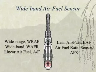
TERMINOLOGY • Wide-band oxygen sensors are used by most vehicle manufacturers to ensure that the exhaust emissions can meet the current standard. • Wide-band oxygen sensors are also called by various names, depending on the vehicle and/or oxygen sensor manufacturer. • The terms used include: • Wide-band oxygen sensor • Broadband oxygen sensor • Wide-range oxygen sensor • Air–fuel ratio (AFR) sensor • Wide-range air–fuel (WRAF) sensor • Lean air–fuel (LAF) sensor • Air–fuel (AF) sensor
FIGURE 25–1 A conventional zirconia oxygen sensor can only reset to exhaust mixtures that are richer or leaner than 14.7:1 (lambda 1.00). NEED FOR WIDE-BAND SENSORSINTRODUCTION • A conventional zirconia oxygen sensor resets to an air–fuel mixture of either richer or leaner than 14.7:1. • This means that the sensor cannot be used to detect the exact air–fuel mixture.
NEED FOR WIDE-BAND SENSORSPURPOSE AND FUNCTION • A wide-band oxygen sensor is capable of supplying air–fuel ratio information to the PCM over a much broader range. • The use of a wide-band oxygen sensor compared with a conventional zirconia oxygen sensor differs as follows: • Able to detect exhaust air–fuel ratio from as rich as 10:1 and as lean as 23:1 in some cases. • Cold-start activity within as little as 10 seconds.
How Quickly Can a Wide-Band Oxygen Sensor Achieve Closed Loop? • In a Toyota Highlander hybrid electric vehicle, the gasoline engine start is delayed for a short time when first started. It is capable of being driven immediately using electric power alone and the oxygen sensor heaters are turned on at first start. The gasoline engine often achieves closed loop operation during cranking because the oxygen sensors are fully warm and ready to go at the same time the engine is started. Having the gasoline engine achieve closed loop quickly, allows it to meet the stringent SULEV standards.
CONVENTIONAL O2S REVIEWNARROW BAND • A conventional zirconia oxygen sensor (O2S) is only able to detect if the exhaust is richer or leaner than 14.7:1. • A conventional oxygen sensor is therefore referred to as: • 2-step sensor • Narrow band sensor • The voltage value where a zirconia oxygen sensor switches from rich to lean or from lean to rich is 0.450 V (450 mV). • Above 0.450 V = rich • Below 0.450 V = lean
FIGURE 25–2 (a) When the exhaust is lean, the output of a zirconia oxygen sensor is below 450 mV. (b) When the exhaust is rich, the output of a zirconia oxygen sensor is above 450 mV. CONVENTIONAL O2S REVIEWNARROW BAND
CONVENTIONAL O2S REVIEWCONSTRUCTION • A typical zirconia oxygen sensor has the sensing element in the shape of a thimble and is often referred to as: • Thimble design • Cup design • Finger design
FIGURE 25–3 Most conventional zirconia oxygen sensors and some wide-band oxygen sensors use the cup-type design. CONVENTIONAL O2S REVIEWCONSTRUCTION
FIGURE 25–4 A typical heated zirconia oxygen sensor, showing the sensor signal circuit that uses the outer (exhaust) electrode as negative and the ambient air side electrode as the positive. CONVENTIONAL O2S REVIEWCONSTRUCTION • There are also two porous platinum electrodes, which have the following functions: • Exhaust side electrode • Ambient side electrode
CONVENTIONAL O2S REVIEWHEATER CIRCUITS • The heater circuit on conventional oxygen sensors requires 0.8 to 2.0 amperes and it keeps the sensor at about 600°F (315°C). • A wide-band oxygen sensor operates at a higher temperature than a conventional HO2S from 1,200°F to 1,400°F (650°C to 760°C). • The amount of electrical current needed for a wideband oxygen sensor is about 8 to 10 amperes.
CONVENTIONAL O2S REVIEWPLANAR DESIGN • A conventional oxygen sensor can be constructed using a planar design instead of the thimble-type design. • A planar design has the following features: • The elements including the zirconia electrolyte and the two electrodes and heater are stacked together in a flattype design. • The planar design allows faster warm-up because the heater is in direct contact with the other elements. • Planar oxygen sensors are the most commonly used. Some planar designs are used as a conventional narrowband oxygen sensor.
FIGURE 25–5 A planar design zirconia oxygen sensor places all of the elements together, which allows the sensor to reach operating temperature quickly. CONVENTIONAL O2S REVIEWPLANAR DESIGN • Another name for a conventional oxygen sensor is a Nernst cell. • The Nernst cell is named for Walther Nernst, 1864–1941, a German physicist known for his work in electrochemistry.
DUAL CELL PLANAR WIDEBAND SENSOR OPERATION • In a conventional zirconia oxygen sensor, a bias or reference voltage can be applied to the two platinum electrodes, and then oxygen ions can be forced (pumped) from the ambient reference air side to the exhaust side of the sensor. • If the polarity is reversed, the oxygen ion can be forced to travel in the opposite direction.
DUAL CELL PLANAR WIDEBAND SENSOR OPERATION • A dual cell planar-type wide-band oxygen sensor is made like a conventional planar O2S and is labeled Nernst cell. • Above the Nernst cell is another zirconia layer with two electrodes, which is called the pump cell. • The two cells share a common ground, which is called the reference. • There are two internal chambers: • The air reference chamber is exposed to ambient air. • The diffusion chamber is exposed to the exhaust gases.
FIGURE 25–6 The reference electrodes are shared by the Nernst cell and the pump cell. DUAL CELL PLANAR WIDEBAND SENSOR OPERATION
DUAL CELL PLANAR WIDEBAND SENSOR OPERATION • STOICHIOMETRIC • When the exhaust is at stoichiometric (14.7:1 air–fuel ratio), the voltage of the Nernst cell is 450 mV (0.450 V). • The voltage between the diffusion chamber and the air reference chamber changes from 0.450 V. • This voltage will be: • Higher if the exhaust is rich • Lower if the exhaust is lean • RICH EXHAUST • LEAN EXHAUST
FIGURE 25–7 When the exhaust is rich, the PCM applies a negative current into the pump cell. DUAL CELL PLANAR WIDEBAND SENSOR OPERATION
FIGURE 25–8 When the exhaust is lean, the PCM applies a positive current into the pump cell. DUAL CELL PLANAR WIDEBAND SENSOR OPERATION
DUAL CELL DIAGNOSISSCAN TOOL DIAGNOSIS • Most service information specifies that a scan tool be used to check the wide-band oxygen sensor. • This is because the PCM performs tests of the unit and can identify faults. • However, even wide-band oxygen sensors can be fooled if there is an exhaust manifold leak or other fault which could lead to false or inaccurate readings. • If the oxygen sensor reading is false, the PCM will command an incorrect amount of fuel. • The scan data shown on a generic (global) OBD-II scan tool will often be different than the reading on the factory scan tool.
DUAL CELL DIAGNOSISSCAN TOOL DATA (PID) • The following information will be displayed on a scan tool when looking at data for a wide-band oxygen sensor:
DIGITAL MULTIMETER TESTING • When testing a wide-band oxygen sensor for proper operation, perform the following steps: • STEP 1 Check service information and determine the circuit and connector terminal identification. • STEP 2 Measure the calibration resistor. While the value of this resistor can vary widely, depending on the type of sensor, the calibrating resistor should still be checked for opens and shorts. • STEP 3 Measure the heater circuit for proper resistance or current flow. • STEP 4 Measure the reference voltage relative to ground. This can vary but is generally 2.4 to 2.6 volts. • STEP 5 Using jumper wires, connect an ammeter and measure the current in the pump cell control wire.
FIGURE 25–9 Testing a dual cell wideband oxygen sensor can be done using a voltmeter or a scope. The meter reading is attached to the Nernst cell and should read stoichiometric (450 mV) at all times. The scope is showing activity to the pump cell with commands from the PCM to keep the Nernst cell at 14.7:1 air–fuel ratio. DIGITAL MULTIMETER TESTING • RICH EXHAUST (LAMBDA LESS THAN 1.00) • LEAN EXHAUST (LAMBDA HIGHER THAN 1.00)
SINGLE CELL WIDE-BAND OXYGEN SENSORSCONSTRUCTION • A typical single cell wide-band oxygen sensor looks similar to a conventional four-wire zirconia oxygen sensor. • The typical single cell wide-band oxygen sensor, usually called an air–fuel ratio sensor, has the following construction features: • Can be made using the cup or planar design • Oxygen (O2) is pumped into the diffusion layer similar to the operation of a dual cell wide-band oxygen sensor. • Current flow reverses positive and negative • Consists of two cell wires and two heater wires (power and ground) • The heater usually requires 6 amperes and the ground side is pulse-width modulated.
FIGURE 25–10 A single cell wide-band oxygen sensor has four wires with two for the heater and two for the sensor itself. The voltage applied to the sensor is 0.4 volt (3.3 - 2.9 = 0.4) across the two leads of the sensor. SINGLE CELL WIDE-BAND OXYGEN SENSORSCONSTRUCTION
SINGLE CELL WIDE-BAND OXYGEN SENSORSTESTING WITH A MILLIAMMETER • The PCM controls the single cell wide-band oxygen sensor by maintaining a voltage difference of 300 mV (0.3 V) between the two sensor leads. • The PCM keeps the voltage difference constant under all operating conditions by increasing or decreasing current between the element of the cell. • Zero (0 mA) represents lambda or stoichiometric air–fuel ratio of 14.7:1 • + 10 mA indicates a lean condition • - 10 mA indicates a rich condition
FIGURE 25–11 The scan tool can display various voltage but will often show 3.3 volts because the PCM is controlling the sensor by applying a low current to the sensor to achieve balance. SINGLE CELL WIDE-BAND OXYGEN SENSORSTESTING USING A SCAN TOOL • A scan tool will display a voltage reading but can vary depending on the type and maker of scan tool.
WIDE-BAND OXYGEN SENSOR PATTERN FAILURES • Wide-band oxygen sensors have a long life but can fail. • Most of the failures will cause a diagnostic trouble code (DTC) to set, usually causing the malfunction indicator (check engine) lamp to light. • However, one type of failure may not set a DTC when the following occurs: • 1. Voltage from the heater circuit bleeds into the Nernst cell. • 2. This voltage will cause the engine to operate extremely lean and may or may not set a diagnostic trouble code. • 3. When testing indicates an extremely lean condition, unplug the connector to the oxygen sensor. If the engine starts to operate correctly with the sensor unplugged, this is confirmation that the wide-band oxygen sensor has failed and requires replacement.
SUMMARY • Wide-band oxygen sensors are known by many different terms, including: • Broadband oxygen sensor • Wide-range oxygen sensor • Air–fuel ratio (AFR) sensor • Wide-range air–fuel (WRAF) sensor • Lean air–fuel (LAF) sensor • Air–fuel (AF) sensor • Wide-band oxygen sensors are manufactured using a cup or planar design and are dual cell or single cell design. • A wide-band oxygen sensor is capable of furnishing the PCM with exhaust air–fuel ratios as rich as 10:1 and as lean as 23:1. • The use of a wide-band oxygen sensor allows the engine to achieve more stringent exhaust emission standards. • A conventional zirconia oxygen sensor can be made in a cup shape or planar design and is sometimes called a narrow band or 2-step sensor.
SUMMARY • The heater used on a conventional zirconia oxygen sensor uses up to 2 amperes and heats the sensor to about 600°F (315°C). A broadband sensor heater has to heat the sensor to 1,200°F to 1,400°F (650°C to 760°C) and requires up to 8 to 10 amperes. • A typical dual cell wide-band oxygen sensor uses the PCM to apply a current to the pump cell to keep the Nernst cell at 14.7:1. • When the exhaust is rich, the PCM applies a negative current to the pump cell. • When the exhaust is lean, the PCM applies a positive current to the pump cell. • Wide-band oxygen sensors can also be made using a single cell design. • Wide-band oxygen sensors can be best tested using a scan tool, but dual cell sensors can be checked with a voltmeter or scope. Single cell sensors can be checked using a milliammeter.
REVIEW QUESTIONS • What type of construction is used to make wide-band oxygen sensors? • Why are wide-band oxygen sensors used instead of conventional zirconia sensors? • How is the heater different for a wide-band oxygen sensor compared with a conventional zirconia oxygen sensor? • How does a wide-range oxygen sensor work? • How can a wide-band oxygen sensor be tested?
CHAPTER QUIZ 1. A wide-band oxygen sensor was first used on a Honda in what model year? • 1992 • 1996 • 2000 • 2006
CHAPTER QUIZ 2. A wide-band oxygen sensor is capable of detecting the air–fuel mixture in the exhaust from ________ (rich) to ________ (lean). • 12:1 to 15:1 • 13:1 to 16.7:1 • 10:1 to 23:1 • 8:1 to 18:1
CHAPTER QUIZ 3. A conventional zirconia oxygen sensor can be made with what designs? • Cup and thimble • Cup and planar • Finger and thimble • Dual cell and single cell
CHAPTER QUIZ 4. A wide-band oxygen sensor can be made using what design? • Cup and thimble • Cup and planar • Finger and thimble • Dual cell and single cell
CHAPTER QUIZ 5. A wide-band oxygen sensor heater could draw how much current (amperes)? • 0.8 to 2.0 A • 2 to 4 A • 6 to 8 A • 8 to 10 A
CHAPTER QUIZ 6. A wide-band oxygen sensor needs to be heated to what operating temperature? • 600°F (315°C) • 800°F (427°C) • 1,400°F (760°C) • 2,000°F (1,093°C)
CHAPTER QUIZ 7. The two internal chambers of a dual cell wide-band oxygen sensor include ________. • Single and dual • Nernst and pump • Air reference and diffusion • Inside and outside
CHAPTER QUIZ 8. When the exhaust is rich, the PCM applies a ________ current into the pump cell. • Positive • Negative
CHAPTER QUIZ 9. When the exhaust is lean, the PCM applies a ________ current into the pump cell. • Positive • Negative
CHAPTER QUIZ 10. A dual cell wide-band oxygen sensor can be tested using a ________. • Scan tool • Voltmeter • Scope • All of the above