Download
1 / 16
170 likes | 392 Vues
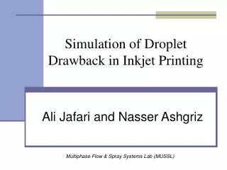
Simulation of Droplet Drawback in Inkjet Printing. Multiphase Flow & Spray Systems Lab (MUSSL). Ali Jafari and Nasser Ashgriz. Motivation. Investigate the interaction between two impacting droplets (drawback)

E N D
Simulation of Droplet Drawback in Inkjet Printing Multiphase Flow & Spray Systems Lab (MUSSL) Ali Jafari and Nasser Ashgriz
Motivation • Investigate the interaction between two impacting droplets (drawback) • Investigate the effect of different parameters and liquid properties on the final droplet shapes (coalesced or not coalesced drops)
Overview • Basic assumptions • laminar and incompressible fluid flow • density constant • Involved mechanisms • fluid dynamics: viscous and capillary effects • Solidification is not considered
Governing Equations • Continuity and momentum equations • Volume of Fluid (VOF)
Two-fluid VOF method based on Piecewise Linear Interface Calculation (PLIC) algorithm. 1 1 1 .68 0 1 1 1 .42 0 A sample “F” field .92 .09 1 1 0 1 0 0 .85 .35 .09 0 0 0 .31 0 0 0 0 0 Interface Tracking • Procedure: • Surface Reconstruction • Use F-field to determine cell “normal” • Determine “case” using normal • Position plane with known slope based upon volume fraction • Compute plane area and vertices • Fluid Advection • Compute flux across cell side (case dependent) • Operator Split (i.e. do for x, y and z sweeps)
Validation: comp. with Fujimoto’s experiments Single water droplet impaction on a surface D=0.56 mm, V=2.65
Simulation parameters • 20 cells per radius • ρ=997 kg/m3 • μ=.000891 kg/m.s • D=40 μm • V=5 m/s • σ=0.073 N/m • Ө=90º
Non-coalesc., Δt=30 μs, Δx=58.5 μm Times: 0, 9, 25, 30, 36, 43, 49, and 60 μs respectively
Coalesc., Δt=30 μs, Δx=57.5 μm Times: 0, 9, 25, 30, 36, 43, 49, and 60 μs respectively
Non-coalesc., Δt=25 μs, Δx=56 μm Times: 0, 9, 25, 30, 36, 43, 49, and 60 μs respectively
Coalesc., Δt=25 μs, Δx=55 μm Times: 0, 9, 25, 30, 36, 43, 49, and 60 μs respectively
Velocity field (non-coalescence) Velocity distribution for case 1, Δt=30 μs, Δx=58 μm at times 36, 40, 43, 45, 49, and 60 μs respectively
Velocity field (coalescence) Velocity distribution for case 1, Δt=30 μs, Δx=57.5 μm at times 36, 40, 43, 45, 49, and 60 μs respectively.
Coalescence case 2: effect of timing Case 2, Δt=25 μs, Δx=55 μm at times 30, 34, 36, 38, 49, and 60 μs respectively.
Non-dim. Pressure contours Δt=30 μs, Δx=57.5 μm at times 43, 45, and 60 μs respectively Δt=30 μs, Δx=58 μm at times 40, 43, and 60 μs respectively.
Conclusions • Drawback is sensitive to • Drop spacing • Impact velocity • Contact angle • Inter-drop time • Small changes in any of the above parameters may result in coalescing or non-coalescing drops: e.g. for Δt=25 μs, coalescence at drop spacing of 55 m; no coalescence at 56 m • Further investigation of all important cases and parameters is planned and from these data, theoretical relations for the threshold of coalescence and non-coalescence would be developed.