Download
1 / 96
960 likes | 1.15k Vues
The Making of the BOL-0 @NIKHEF. Introduction Assembly Station Sag adjustment Gluing BOL-0 Temperature studies Summary. NIKHEF ATLAS MUON group : H. vdGraaf, F.Linde, G. Massaro, M. Vreeswijk, P. Werneke. ATLAS-Muon.

E N D
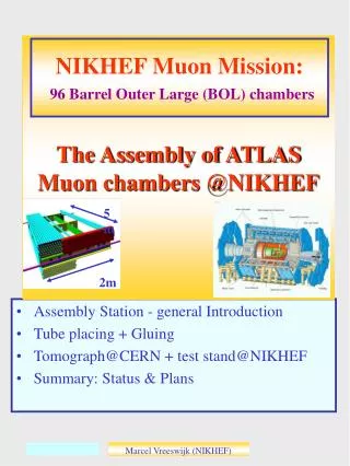
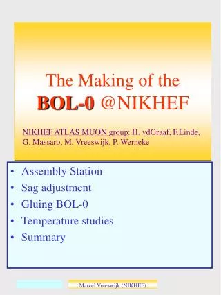
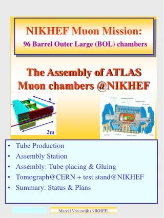
The Making of the BOL-0 @NIKHEF • Introduction • Assembly Station • Sag adjustment • Gluing BOL-0 • Temperature studies • Summary NIKHEF ATLAS MUON group: H. vdGraaf, F.Linde, G. Massaro, M. Vreeswijk, P. Werneke Marcel Vreeswijk (NIKHEF)
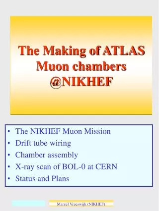
ATLAS-Muon • Muon system with air core toroid aims at 50um spatial (sagitta) precision in bending plane. • Achieved by: • excellent alignment ~20um • precise drift tube chambers ~20um (RMS) West side has expansion length o 0.1m in Xras Marcel Vreeswijk (NIKHEF) s
ATLAS-Muon • Alignment based on RASNIK Relative measurement of three points • Alignment scheme: In-Plane NIKHEF will produce the Barrel Outer Large chambers, 2mx5m, BOL (~100) This talk: BOL-0 Projective alignment Chambers consist of spacer + 2x3 drift tube layers In-Plane system monitors internal chamber deformations Projective alignment monitors chamber to chamber movements West side has expansion length o 0.1m in Xras Marcel Vreeswijk (NIKHEF) s
Assembly Station • Granite table: 6m x 2.5m Situation mid 99 East Z Up Y North X • Three bare Cross-Plates are positioned on the station, carried by sphere holders • The combs which will support the tubes are also visible • In the background: wiring station, Quality Control setup(s) West side has expansion length o 0.1m in Xras Marcel Vreeswijk (NIKHEF) s
Precision Mechanics • intrinsic accuracy better than 10um • Positioning combs and sphere holders • Tools: • Laser + optics (straightness combs), • silicon sensor (to line up combs), • Slof (height-meter), • tilt-meters (check Torque), • Balmonitor (dZ between multilayers) The quantities which affect the wire positions are checked and found to be precise within 10um Granite table has sag of 25um + 10um light on/off West side has expansion length o 0.1m in Xras Marcel Vreeswijk (NIKHEF) s
Spacer • Spacer monitored by RASAS Situation mid 2000 No Flexo In-plane lens NIKHEF Comb longbeam RASAS tower Xplate In-plane mask Frascati comb ‘Ear’ with sphere and RASAS-MASK Sphere tower with changeable block to adapt to tube layers West side has expansion length o 0.1m in Xras Marcel Vreeswijk (NIKHEF) s
Sag Compensation • Sag compensation has been used manually. • Three pressures: 2 x outer (practically equal) and inner Xplates. Sagcompen-sation tower Additional weight for safety After consistent results we adjusted the sag to obtain (almost) symmetric weight distribution Marcel Vreeswijk (NIKHEF) s
Sag Compensation • Xplate sag before adjustment Chamber up Chamber (upside) down Asymmetric sag Xplates, due to asymmetric weight distribution during gluing spacer -> Adjust Marcel Vreeswijk (NIKHEF) s
Sag Adjustment • Xplate sag after adjustment Chamber up Chamber (upside) down After sag adjustment we observe (almost) symmetric sags for chamber up and down positions Marcel Vreeswijk (NIKHEF) s
Sag Adjustment+Compensation Chamber before adjustement and compensation Chamber after compensation Marcel Vreeswijk (NIKHEF) s
Assembly Station +Spacer Summary: • Assembly Station alignment good for wire position to the 10um level. • Asymmetric distribution long-beams adjusted successfully. • Sag (compensation) of cross plates understood within 20um. • Observed sag of granite table of about 30um Marcel Vreeswijk (NIKHEF) s
Quality Control on drift tubes, specs: • Wire position: |Z,Y|<25um • Wire tension: 350gr+-5% (+batch 275gr) • Leak rate: He 2.5 x 10⁻⁸ lb/s (official: Ar 1.0 x 10⁻⁸ ) • HV check: <20nA @3000V By mistake Tube wiring + QC • Wiring Machine (NIKHEF) Marcel Vreeswijk (NIKHEF)
QC-Wire position Drift Tube Coil EndPlug • Wire position: • |Y,Z|<25um Rejection 2% 1 tube was found with R>100um. A destructive check revealed: no twister in endplug Marcel Vreeswijk (NIKHEF) s
QC-Wire tension • Quality Control on drift tubes, specs: • Wire tension: 350gr+-5% (+batch 275gr) Rejection 5% (3%). >1 month after production, creep of the order of 1gr over >1 month Marcel Vreeswijk (NIKHEF) s
QC-Leak Rate • Quality Control on drift tubes, specs: • Leak rate: He (4 bar) 2.5 x 10⁻⁸ bl/s • (official: Ar(3 bar) 1.0 x 10⁻⁸ ) 10-1 Rejection 4% Marcel Vreeswijk (NIKHEF) s
QC HV Check • Quality Control on drift tubes, specs • HV 3000V , current <2.0nA Overcurrent tubes Rejection 4% Marcel Vreeswijk (NIKHEF) s
Gluing BOL-0 • In the BOL-0 all tubes passed the QC. Different wire tensions are used. • Wire tension for layer 1-4: 350 gr (nominal) • For layer 5: 275 gr • layer 6: 275gr + 5 tubes with 350gr (interesting check X-ray tomograph) Marcel Vreeswijk (NIKHEF) s
tube tube Gluing BOL-0 • Problems: • Nozzle mounting very critical • Central glue ropes between tubes not uniform/symmetric glue Bigger central glue cilinder • Solutions: • Reduce Glue machine X speed by two (now ~10m/s) • Double amount of glue 103 (instead of 106, 2011) for central ropes which is more fluid • (keep nominal amount of glue for side ropes, 106) Glue stop for tape Marcel Vreeswijk (NIKHEF) s
Start glue Start glue Gluing BOL-0 • Stability Xplates during gluing Layer 1 Yrasnik=2 x Sag Layer 1: dSag=7um Layer 2 Start glue Layer 3 Layer 2: dSag=10um • The sag of the xplates in layer 1 and 2 change in time. Glue crimp? Temperature? • Layer 3,4,5,6: Sag stable Marcel Vreeswijk (NIKHEF) s
NW NE Global X Global Z, RASAS X SW SE Gluing BOL-0 • RASAS monitors Global Z • Relatively large Z movement layer 6 (spacer floats on glue?) Global Y (up) Lever arm in stacking block • Stability in Y appears very good ( for some layers the RASAS indicated problems which could be online corrected) Marcel Vreeswijk (NIKHEF) s
BOL-0 Thickness Multi-layers BOL0 has tape (50um) between tubes at one side Much work.. 2 layers • Tubes press glue away? • Tubes deform? • Affects precision praxial platforms! 3 layers Tape seems to improve tube distance Marcel Vreeswijk (NIKHEF) s
Xplate Yrasnik= 2 x sag BOL-0 Heat Studies (No flexoos in BOL-0) The BOL-0 was covered with heat blankets, producing 50W/m2 Inplane Yrasnik= 2 x sag Gradient between MLs: 2.5 to 4 oC Sag of Chamber: 200um 50 to 80 um/oC= acceptable Sag of xplate: 25um 6 tp 10 um/oC = acceptable Marcel Vreeswijk (NIKHEF) s
Summary • We have constructed BOL-0 at NIKHEF • NEXT • Chamber will be scanned at CERN in Xray tomograph • Automise QC setups. Most notably: leak rate + HV (tubbies) • If OK, Production starts April 1th, 2001 • Produce chamber/2weeks Marcel Vreeswijk (NIKHEF) s
Production • Production of 100 BOL chambers will start April 1th • How many people are involved? • People who do the work • People who do the ‘visual inspections’ • And ‘stuurlui’ Marcel Vreeswijk (NIKHEF)
Assembly Station • Accuracy combs and sphere holders • The intrinsic accuracy of mechanics is good • The granite table has a relatively large sag of about 25um. Additional effects of 10um with light on and off (temperature gradient) • Positioning combs and sphere holders • Tools: • Laser + optics (straightness combs), • silicon sensor (to line up combs), • Slof (height-meter), • tilt-meters (check Torque), • Balmonitor (dZ between multilayers) West side has expansion length o 0.1m in Xras Marcel Vreeswijk (NIKHEF)
Assembly Station • The Balmonitor is a Cross-Plate equipped with lenses. Each lens is combined with a ‘fork’ on the combs to form a RASNIK system • The Balmonitor measures the Z and Y difference between Sphere tower and Comb between North and South. (Z difference between Multilayers) • Additionally the Balmonitor is used to check for height difference between sphere towers at the reference and non-reference side (West/East) West side has expansion length o 0.1m in Xras Marcel Vreeswijk (NIKHEF) s
Assembly Station West side has expansion length o 0.1m in Xras Marcel Vreeswijk (NIKHEF)
Assembly Station West side has expansion length o 0.1m in Xras Marcel Vreeswijk (NIKHEF)
Gluing BOL-0 Layer 1 Layer 2 Marcel Vreeswijk (NIKHEF)
RASAS • RASAS- stacking The stacking has been checked using the RASAS monitors. The bare spacer has been put into A+, A-, C+ and C- orientations for the 3 stacking blocks The nominal steps are dY=26.011 um and dZ=15.017 um After a fit of the Mask-orientations (4), the residuals are shown below. Marcel Vreeswijk (NIKHEF)
um Assembly Station • RASAS- block deviations The fitted block deviations are within 10um as expected from measurements with a 3D coordinate machine. • The expectation values of the masks are extracted from: • CCD angles from dedicated calibration, 0.1 mrad • RASNIK measurements of relative angle from the MASK and CCD (0.1 mrad). Inmrad Marcel Vreeswijk (NIKHEF)
Assembly Station • RASAS -temperature stability The Xplates are made off aluminum and expand about 24um/C/m. East side has expansion length of 2.4m in Xras Marcel Vreeswijk (NIKHEF)
XPlate RASNIKs • The calibration (zero level) of the Xplate rasniks can be extracted from: 1) The RASNIK reading for the up and down position of the bare Xplates before gluing the spacer. Problem: old data, components touched. 2) The response for the up and down position (A+,A-) of the spacer. Problem: large effects due to large gravitational force, leading to possibly large second order effects 3) The RASNIK response for the up and down position of the airborne spacer. Problem:hysteres due to bad design of crane beams. West side has expansion length o 0.1m in Xras Marcel Vreeswijk (NIKHEF)
XPlate RASNIKs • calibration Xplate rasniks, by rotation of airborne (horizontal) spacer This method yields consistent results compared to up/down positions of the bare Xplates West side has expansion length o 0.1m in Xras Marcel Vreeswijk (NIKHEF)
In-Plane RASNIKs • The calibration of the In-Plane (Y) is extracted from data in A+, A-, C+, C- positions. • A model to account for asymmetric weight distribution over the XPs in the + and -- orientations has been used to fit the data. Data of the four in-plane systems: Data Although steps appear large and uncontrolled, the data is reasonably well described by the model (10 um) Model West side has expansion length o 0.1m in Xras Marcel Vreeswijk (NIKHEF)
In-Plane RASNIKs • Model Parameters Uncertainties 10% Implications: 1) Sag of Xplates as function of additional weigth consistent with data. FEA predicts slope of 0.56!!!!! 2) Sphere block in centre are off in height by appr. 30um as confirmed by laser+Si-sensor and also qualitatively by optical alignment tool!!!!! 3) In A+ position, when the spacer was glued, longbeam weight on outer Xplates!!!! West side has expansion length o 0.1m in Xras Marcel Vreeswijk (NIKHEF)
Sag Compensation Marcel Vreeswijk (NIKHEF)
Sag Compensation 0.4 bar Marcel Vreeswijk (NIKHEF)
Sag Compensation • Shape without sag compensation Marcel Vreeswijk (NIKHEF)
Sag Compensation • Shape with sag compensation Marcel Vreeswijk (NIKHEF)
The road to BOL-0 Marcel Vreeswijk (NIKHEF)
Gluing BOL-0 • Layer 3 Marcel Vreeswijk (NIKHEF)
In-Plane RASNIKs • The calibration of the In-Plane (Y) is extracted from data in A+, A-, C+, C- positions.. West side has expansion length o 0.1m in Xras Marcel Vreeswijk (NIKHEF)
tube Gluing BOL-0 • Result for side (106) and central (103) ropes Central rope Central rope Central rope Central rope Central rope, sometimes bad (stability glue unit?) Marcel Vreeswijk (NIKHEF)
Hunting the Higgsby online B-tagging • The Standard Model • The Higgs particle; recent results!!!! • The D0 experiment • The proposal • Costs • Conclusions Marcel Vreeswijk (NIKHEF)
The Standard Model • The Standard Model=Relativistic Quantum Field theory with Local Gauge SymmetrySU(2) x U(1) • Higgs mechanism endows particles with mass, while maintaining Gauge Symmetry. • The Higgs mechanism gives rise to a particle called the Higgs Boson, which has been elusive so far. • Theoretical Mass constraints: • An upper limit is related to unitary and set by the Higgs self coupling. • The stability of the Higgs potential provides a lower limit. • Otherwise: new physics has to become manifest at some scale L!!!! Not allowed Not allowed Allowed Marcel Vreeswijk (NIKHEF)
The Higgs Particle The mass of the Higgs can be predicted by the combination of precision measurements (from LEP) which are sensitive to higher order Quantum Corrections that involve a Higgs Boson. b b Z Z Higgs t b b MHiggs<245 GeV The yellow band is excluded by the direct searches at LEP Marcel Vreeswijk (NIKHEF)
e H Z e Z The Higgs Particle The LEP programme just has been extended by one month (until November 2th). The LEP experiments have reported an excess of events above other standard model processes, compatible with a Higgs boson of about 114 GeV! Direct searches at LEP Signature: 4 jets (2 with B-meson) Z -> qq H -> bb Invariant mass of B quark jets. (in red: theoretical contributions for Mhiggs=114GeV) Deviation from other SM processes. (a handful events…) However, observed Xsection to high. Marcel Vreeswijk (NIKHEF)
Background Data Signal The Higgs Particle Direct searches at LEP (ALEPH) Signal+Background hypothesis: Likelihood Ratio (signal/background) • The Higgs might be around the corner. • LEP will most certainly not be granted another year (the future of CERN is chosen to be LHC from 2005, which can do the job better …. but, TEVATRON in 2001 gets the first shot) • Optimistically, if LEP claims a 3-4 std discovery, it will be shared with TEVATRON. The TEVATRON (and later LHC) will have the great task to study what was discovered. Marcel Vreeswijk (NIKHEF)
The Higgs Particle • The Higgs might be around the corner. • LEP will most certainly not be granted another year (the future of CERN is chosen to be LHC from 2005, which can do the job better …. but, TEVATRON in 2001 gets the first shot) • Optimistically, if LEP claims a 3-4 std discovery, it will be shared with TEVATRON. The TEVATRON (and later LHC) will have the great task to study what was discovered. This talk: concentrate on the search for a low mass Higgs (M<140 GeV) at D0 (TEVATRON) Marcel Vreeswijk (NIKHEF)