Download
1 / 21
210 likes | 370 Vues
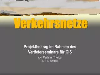
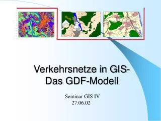
Verkehrsnetze in GIS- Das GDF-Modell. Seminar GIS IV 27.06.02. Inhaltsübersicht:. 1. Einleitung 1.1 Warum GDF ? 1.2 Was ist GDF ?. 2. Features und Levels in GDF 3. Level-0-Topologie 4. ´ Roads and Ferries´ 5. Attribute 6. Relationen. 1.Einleitung.

E N D
Verkehrsnetze in GIS-Das GDF-Modell Seminar GIS IV 27.06.02
Inhaltsübersicht: 1. Einleitung 1.1 Warum GDF ? 1.2 Was ist GDF ? 2. Features und Levels in GDF 3. Level-0-Topologie 4. ´Roads and Ferries´ 5. Attribute 6. Relationen
1.Einleitung 1.1 Warum GDF ? • für Routenplanung muß Zusammenhang zw.Geometrie • des Straßennetzes und Positionsdaten bekannt sein • digitale Straßenkarte, die Geometrie mit • zusätzlichen verkehrsrelevanten Informationen verknüpft • gemeinsame digitale Straßenkarte für alle Anwendungen • Standardisierung der Datenerfassung und des Formats für • den Datenaustausch • GDF-Standard als Grundlage für digitale Straßenkarten
1.2 Was ist GDF ? I - die Abkürzung für geographic data files - Standard für die Beschreibung bzw. Definition von Daten für Straßennetzwerke und deren Austausch - standardisiertes geometrisches und topologisches Modell für Straßendaten - enthält auch Regeln zur Datenerfassung, -verwaltung und -präsentation • GDF-Daten im Austauschformat für jeweilige Anwendung in das • dafür vorgesehene System (z.B. Fahrzeugnavigationssystem) • überführen
1.2 Was ist GDF ? II - Anwendungsbereiche: Fahrzeugnavigation, Verkehrsleitsysteme, Flottenmanagement etc. • GDF mittlerweile von der ISO ( International Organisation • for Standardisation ) als weltweiter Standard anerkannt • wird dort weiterentwickelt in ISO\TC204 • ( Traffic Information and Control Systems ) • - Firmen TeleAtlas und NavTech erfassen GDF-Daten • Seit 1995 GDF-Daten für Deutschland flächendeckend • GDF- Dokumentation 4.0 ausführl.Beschreibung d.Standards
2. Features und Levels in GDF Features -´real world objects´ Complex Features Level 2 Verbindung zur Realität Aggregation Simple Features Level 1 Point Feature Line Feature Area Feature node edge face Geometrie +Topologie Level 0
3. Level-0-Topologie hier kein Knoten (node) Connectivity Topology: - Topologische Relationen zw. 0-dim und 1-dim Objekten Node - 2-dim Objekte durch Umring Edges - Nodes und Edges formen nicht-ebenen Graph - z.B.: Straßen bilden keine Kreuzung, sondern verlaufen durch eine Brücke übereinander
3. Level-0-Topologie Connectivity Topology: z y Edges x Kanten verlaufen übereinander
3. Level-0-Topologie Edge Full Topology: Node - Topologische Relationen zw. 0-dim, 1-dim und 2-dim Objekten - 2-dim Objekte durch Faces - Nodes und Edges formen ebenen Graph - D.h.: Flächeninformationen werden integriert
3. Level-0-Topologie Non-explicit topology: - Topologische Relationen nur über Koordinatenwerte - nur geometrische Informationen • hier nicht nodes, edges, faces, • sondern dots, polylines, polygons • auf Level 0
4. Roads and Ferries Feature Themes in GDF ______
4. Roads and Ferries • - Straßennetzwerk in Level 1 und Level 2 repräsentiert • Level-2-Repräsentation bei vereinfachter Beschreibung • des Straßennetzwerks Intersection Road Level 2 Junction Road Element Level 1
Road enthält 2 Road Elements: Road Element Level 1 Junction Inter- section Level 2 Road
Road enthält keine Road Elements Road Element Level 1 Junction Road Level 2 Intersection
5. Attribute Simple Attributes:haben eine Komponente Composite Attributes:haben mehrere Komponenten Sub-Attributes Restrictive Sub-Attributes:beschränken Gültigkeit des mit ihm verbundenen Attributs können nie allein stehen Segmented Attributes: nur für bestimmten Teil eines Features gültig position-from-, position-to-value
Bsp. für Restrictive Sub-Attribute: Validity Period Restr.Sub-Attribute: Validity Period 8.00 – 18.00 Uhr Attribut: Speed Restriction 50 km/h Feature: Road Element Andere Restr.Sub-Attr.: - Validity Direction best. Richtung - Lane Dependent Validity best. Fahrbahn - Street Side best. Straßenseite - Vehicle Type best. Fahrzeugtyp
6. Relationen - nicht-topologische Zusammenhänge -z.B. die Beziehung ´is capital of´ zwischen Paris und Frankreich • meistens Beziehungen zwischen 2 Features -möglich aber auch mehrere Features in einer Beziehung z.B. eine Brücke führt eine Straße über einen Fluß
Prohibited Manoeuvre: Abbiegeverbot L711 J1 L712 L522 J4 L521 L723 Alternative: Restricted Manoeuvre
Priority Manoeuvre: Vorfahrtsregelung L711 L721 L511 J1 J2 L712 L522 L521