Lec 1: Internet Overview
Lec 1: Internet Overview. ECE5650. Intenet. Physical Connectivity Topology Access network and physical media Layered Internet Protocol Stack History. millions of connected computing devices: hosts = end systems running network apps communication links fiber, copper, radio, satellite

Lec 1: Internet Overview
E N D
Presentation Transcript
Lec 1: Internet Overview ECE5650 Overview
Intenet • Physical Connectivity • Topology • Access network and physical media • Layered Internet Protocol Stack • History Overview
millions of connected computing devices: hosts = end systems running network apps communication links fiber, copper, radio, satellite transmission rate = bandwidth routers: forward packets (chunks of data) router workstation server mobile local ISP regional ISP company network What’s the Internet: “nuts and bolts” view Overview
Distributed applications: Web, email, games, e-commerce, file sharing Network protocols: used by applications tocontrol sending, receiving of msgs: TCP, IP, HTTP, FTP, PPP Internet standards RFC: Request for comments IETF: Internet Engineering Task Force Communication services provided to apps: Connectionless unreliable connection-oriented reliable What’s the Internet: a service view Overview
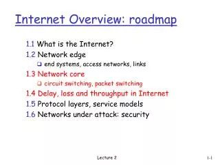
network edge: applications and hosts network core: routers network of networks access networks, physical media: communication links A closer look at network structure: Overview
end systems (hosts): run application programs e.g. Web, email at “edge of network” Programs in end-systems use the serivce of the Internet to send msgs to each other client/server model client host requests, receives service from always-on server; e.g. web, email peer-peer model: minimal (or no) use of dedicated servers e.g. Gnutella, KaZaA, Skype, BitTorrent The network edge: Overview
Physical connectivity of local area networks mesh of interconnected routers Logical connectivity: how is data transferred through net? The Network Core Overview
roughly hierarchical at center: “tier-1” ISPs or Internet backbone networks (e.g., MCI, Sprint, AT&T, Cable and Wireless), national/international coverage, connect to large tier-2 ISPs and to all tier-1 ISPs and many customer networks. NAP Tier-1 providers also interconnect at public Network Access Points (NAPs). Tier-1 providers interconnect (peer) privately Internet structure: network of networks Tier 1 ISP Tier 1 ISP Tier 1 ISP Overview
Commercial Internet ISP Connectivity • Roughly hierarchical • Divided into tiers • Tier-1 ISPs are also called backbone providers, e.g., AT&T, Sprint, UUNet, Level 3, Qwest, Cable & Wireless • An ISP runs (private) Points of Presence (PoP) where its customers and other ISPs connect to it • E.g., MCI has 4,500 PoP • called private peering • ISPs also connect at (public) Network Access Point (NAP) • called public peering Overview
“Tier-2” ISPs: smaller (often regional) ISPs Connect to one or more tier-1 ISPs, possibly other tier-2 ISPs NAPs (Network Access Points) are complex high-speed switching networks often concentrated at a single building. Operated by 3rd party telecom or Internet backbone ISP-1. PoPs (Points of Presence) are private group of routers within each ISP and used to connect it (peer it) with other up/down/equal ISPs and is the new trend in connectivity. NAP Tier-2 ISPs also peer privately with each other, interconnect at public NAPs or private POPs. Tier-2 ISP pays tier-1 ISP for connectivity to rest of Internet, tier-2 ISP is customer of tier-1 provider Tier-2 ISP Tier-2 ISP Tier-2 ISP Tier-2 ISP Tier-2 ISP Internet structure: network of networks Tier 1 ISP Tier 1 ISP Tier 1 ISP Overview
“Tier-3” ISPs and local ISPs last hop (“access”) network (closest to end systems) Tier 3 ISP local ISP local ISP local ISP local ISP local ISP local ISP local ISP local ISP NAP Local and tier- 3 ISPs are customers of higher tier ISPs connecting them to rest of Internet Tier-2 ISP Tier-2 ISP Tier-2 ISP Tier-2 ISP Tier-2 ISP Internet structure: network of networks Tier 1 ISP Tier 1 ISP Tier 1 ISP Overview
a packet passes through many networks! Tier 3 ISP local ISP local ISP local ISP local ISP local ISP local ISP local ISP local ISP NAP Tier-2 ISP Tier-2 ISP Tier-2 ISP Tier-2 ISP Tier-2 ISP Internet structure: network of networks Tier 1 ISP Tier 1 ISP Tier 1 ISP Overview
Tier-1 ISP: e.g., Sprint Introduction
ATT Global Backbone IP Network From http://www.business.att.com Overview
MichNet: Statewide Backbone • Nation’s longest-running regional network • An 2.5 Gigabit (OC48c) backbone, with 24 backbone nodes • Two diverse 2.5 gigabit (2x OC48) to chicago • www.merit.edu/mn Overview
Intenet • Physical Connectivity • Structure • Access network and physical media • Layered Internet Protocol Stack • History Overview
Q: How to connect end systems to edge router? residential access nets institutional access networks (school, company) mobile access networks Keep in mind: bandwidth (bits per second) of access network? shared or dedicated? Access networks and physical media Overview
Dialup via modem Uses existing telephony infrastructure; Home is connected to central office up to 56Kbps direct access to router (often less) Can’t surf and phone at same time: can’t be “always on” Residential access: point to point access central office telephone network Internet homedial-up modem ISPmodem (e.g., AOL) home PC Overview
telephone network • ADSL: asymmetric digital subscriber line • up to 1 Mbps upstream (today typically < 256 kbps) • up to 8 Mbps downstream (today typically < 1 Mbps) • FDM: 50 kHz - 1 MHz for downstream 4 kHz - 50 kHz for upstream 0 kHz - 4 kHz for ordinary telephone Existing phone line:0-4KHz phone; 4-50KHz upstream data; 50KHz-1MHz downstream data Internet home phone DSLAM splitter DSL modem central office home PC Overview
HFC: hybrid fiber coax asymmetric: up to 30Mbps downstream, 2 Mbps upstream network of cable and fiber attaches homes to ISP router homes share access to router so communication activity is visible to each other. deployment: available via cable TV companies Residential access: cable modems Overview
Residential access: cable modems Diagram: http://www.cabledatacomnews.com/cmic/diagram.html Overview
Cable Network Architecture: Overview Typically 500 to 5,000 homes cable headend home cable distribution network (simplified) Overview
Cable Network Architecture: Overview cable headend home cable distribution network (simplified) Overview
server(s) Cable Network Architecture: Overview cable headend home cable distribution network Overview
C O N T R O L D A T A D A T A V I D E O V I D E O V I D E O V I D E O V I D E O V I D E O 5 6 7 8 9 1 2 3 4 Channels Cable Network Architecture: Overview FDM: cable headend home cable distribution network Overview
company/univ local area network (LAN) connects end system to edge router Ethernet: shared or dedicated link connects end system and router 10 Mbs, 100Mbps, Gigabit Ethernet LANs: chapter 5 Company access: local area networks Overview
shared wireless access network connects end system to router via base station aka “access point” wireless LANs: 802.11a/b/g (WiFi): 11 Mbps ~54Mbps 802.11n: 100~200Mbps (theoretically up to 300Mbps) wider-area wireless access provided by telco operator 3G ~ 384 kbps Will it happen?? WAP/GPRS in Europe WiMAX ~100Mbps ~10 miles router base station mobile hosts Wireless access networks Overview
Typical home network components: DSL or cable modem router/firewall/NAT Ethernet wireless access point Home networks wireless laptops to/from cable headend cable modem router/ firewall wireless access point Ethernet Introduction
Bit: propagates betweentransmitter/rcvr pairs physical link: what lies between transmitter & receiver guided media: signals propagate in solid media: copper, fiber, coax unguided media: signals propagate freely, e.g., radio Twisted Pair (TP) two insulated copper wires Category 3: traditional phone wires, 10 Mbps Ethernet Category 5: 100Mbps Ethernet Physical Media Introduction
Coaxial cable: two concentric copper conductors bidirectional baseband: single channel on cable legacy Ethernet broadband: multiple channels on cable HFC Physical Media: coax, fiber Fiber optic cable: • glass fiber carrying light pulses, each pulse a bit • high-speed operation: • high-speed point-to-point transmission (e.g., 10’s-100’s Gps) • low error rate: repeaters spaced far apart ; immune to electromagnetic noise Introduction
signal carried in electromagnetic spectrum no physical “wire” bidirectional propagation environment effects: reflection obstruction by objects interference Physical media: radio Radio link types: • terrestrial microwave • e.g. up to 45 Mbps channels • LAN (e.g., Wifi) • 11Mbps, 54 Mbps • wide-area (e.g., cellular) • 3G cellular: ~ 1 Mbps • satellite • Kbps to 45Mbps channel (or multiple smaller channels) • 270 msec end-end delay • geosynchronous versus low altitude Introduction
Intenet • Physical Connectivity • Topology • Access network and physical media • Layered Internet Protocol Stack • History Overview
human protocols: “what’s the time?” “I have a question” introductions network protocols: machines rather than humans all communication activity in Internet governed by protocols What’s a protocol? A protocol is a set of rules that govens how two or more communicating parties are to interact. It defines: - msg format - order of msgs sent & received - actions taken on msg transmission & receipt Overview
Protocol “Layers” Networks are complex! • many “pieces”: • hosts • routers • links of various media • applications • protocols • hardware, software • Layered Protocol • Modular approach to network functionality • Examples: • Taking an airplane trip • Mailing service Overview
application: supporting network applications FTP, SMTP, HTTP transport: process-process data transfer TCP, UDP network: host-host data transfer IP link: data transfer between neighboring network elements PPP, Ethernet physical: bits “on the wire” application transport network link physical Internet protocol stack Overview
network link physical link physical M M Ht Ht M M Hn Hn Hn Hn Ht Ht Ht Ht M M M M Hl Hl Hl Hl Hl Hl Hn Hn Hn Hn Hn Hn Ht Ht Ht Ht Ht Ht M M M M M M source Encapsulation message application transport network link physical segment datagram frame switch destination application transport network link physical router Overview
Characteristics of Layering • Layering positives: • Each layer relies on services from layer below and exports services to layer above • Interface defines interaction • Hides implementation - layers can change without disturbing other layers (black box) • Layering negatives: duplicate functionality and inter-dependency. Overview
1961: Kleinrock - queueing theory shows effectiveness of packet-switching 1964: Baran - packet-switching in military nets 1967: ARPAnet conceived by Advanced Research Projects Agency 1969: first ARPAnet node operational 1972: ARPAnet demonstrated publicly NCP (Network Control Protocol) first host-host protocol first e-mail program ARPAnet has 15 nodes Internet History 1961-1972: Early packet-switching principles Overview
Initial ARPANET • 1965-1968 • ARPANET plan, implemented by BBN (Bolt, Beranek, Newman): packet switch to build IMP • 1969 • ARPANET commissioned: 4 nodes, 50kbps Overview
Initial Expansion of the ARPANET Dec. 1969 July 1970 Mar. 1971 Apr. 1972 Sept. 1972 Overview RFC 527: ARPAWOCKY; RFC 602: The Stockings Were Hung by the Chimney with Care
1970: ALOHAnet satellite network in Hawaii 1973: Metcalfe’s PhD thesis proposes Ethernet 1974: Cerf and Kahn – archi. for interconnecting networks Initially, named NCP Later, split to TCP/IP late70’s: proprietary architectures: DECnet, SNA, XNA late 70’s: switching fixed length packets (ATM precursor) 1979: ARPAnet has 200 nodes Cerf and Kahn’s internetworking principles: minimalism, autonomy - no internal changes required to interconnect networks best effort service model stateless routers decentralized control define today’s Internet architecture 2005 ACM Turing Award “A protocol for packet network interconnection”, IEEE Trans. on Communications Technology, vol.22(5), 627-641 Internet History 1972-1980: Internetworking, new and proprietary nets Overview
1983: deployment of TCP/IP 1982: SMTP e-mail protocol defined 1983: DNS defined for name-to-IP-address translation 1985: FTP protocol defined 1988: TCP congestion control new national networks: Csnet, BITnet, NSFnet, Minitel 100,000 hosts connected to confederation of networks Internet History 1980-1990: new protocols, a proliferation of networks Overview
Early 1990’s: ARPAnet decommissioned 1991: NSF lifts restrictions on commercial use of NSFnet (decommissioned, 1995) 1992, 1 million hosts early 1990s: Web hypertext [Bush 1945, Nelson 1960’s] HTML, HTTP: Berners-Lee 1994: Mosaic, later Netscape late 1990’s: commercialization of the Web Late 1990’s – 2000’s: more killer apps: instant messaging, peer2peer file sharing (e.g., BitTorrent, YouTube) network security to forefront Today: 400 million users, 150 countries backbone links running at 10 Gbps Internet History 1990, 2000’s: commercialization, the Web, new apps Overview
Growth of the Internet Number of Hosts on the Internet: Aug. 1981 213 Oct. 1984 1,024 Dec. 1987 28,174 Oct. 1990 313,000 Jul. 1993 1,776,000 Jul. 1996 19,540,000 Jul. 1999 56,218,000 Jul. 2004 285,139,000 Jan. 2005 317,646,000 Jul. 2005 353,284,000 About 2B users out of 6.8B people, from 16M in 1995, 350M in 2000,1B in 2005 Overview
Summary • Physical Connectivity • Topology • Access network and physical media • Layered Internet Protocols • History Overview