Lect 11: Memory and I/O Interface and Memory Devices
110 likes | 306 Vues
Lect 11: Memory and I/O Interface and Memory Devices. Memory Interface Circuitry. Memory interface block diagram See Fig 9.25 on page 398 Address latches and buffers ALE (Address Latch Enable) enable-to-output propagation delay (ex: 74F373: 13 ns)

Lect 11: Memory and I/O Interface and Memory Devices
E N D
Presentation Transcript
Memory Interface Circuitry • Memory interface block diagram • See Fig 9.25 on page 398 • Address latches and buffers • ALE (Address Latch Enable) • enable-to-output propagation delay(ex: 74F373: 13 ns) • 74F373, 74F374 : See Fig 9.26, Fig 9.27, Fig 9.28 • Buffering effect : • 386 address lines can sink only 4 mA • F373 latch can sink a maximum of 24 mA • Data Bus Transceivers • DT/R (data transmit/receive) ; DEN (data bus enable) • 74F245 : See Fig 9.30, Fig 9.31 • propagation delay : 7 ~ 8 ns • Buffering Effect: • 386 data lines : 4mA • F245 : 64 mA
Address Decoders • 74F139 dual 2-line-to-4-line decoder • 74F138 single 3-line-to-8-line decoder • Bus Control logic • System Controller • PLAs, GALs, and EPLDs • PALs : bipolar technology - burning out fuse links GALs : CMOS technology - electrically erasable read-only memory (EEROM) EPLDs : CMOS technology - electrically programmable read only memory (EPROM)
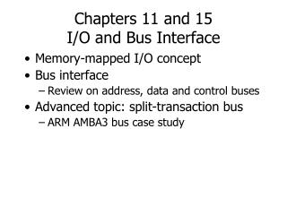
Input/Output • Isolated Input/Output • Isolated I/O space : See Fig 9.47 • page 0 : 0-255 ; direct access • Advantages • Full memory space • Special Instructions - maximize I/O performance • Disadvantages • Restricted Instruction Power • Separate I/O control signals • Memory Mapped Input/Output • Memory mapped I/O : See Fig 9.48 • Advantages • Powerful Instruction set • No I/O control signals • Disadvantages • Part of Memory space is lost • the memory instructions tend to execute slower than those specially designed for isolated I/O
The Isolated I/O Interface • See Fig. 9.49, 9.51
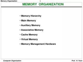
Memory Devices and Subsystem Design • Memory Subsystem Design Read-only Memory Random access read/write memories FLASH memory Wait-state Circuitry Cache memory Cache controller • Read-Only Memory • ROM, PROM, EPROM • ROM BIOS(Basic Input/Output System) • Read Operation : See Fig 10.4 • Standard EPROM ICs : See Fig 10.6, 10.7, 10.9 • Random Access Read/Write Memories • RAM • Static and Dynamic RAMs • SRAM • DRAM : refreshing
Static RAM • Block Diagram and Standard SRAM ICs : See Fig 10.11, 10.12, 10.13, 10.16 • Read/Write Operation : See Fig 10.17, 10.18 • Dynamic RAM • Standard DRAM ICs : See Fig 10.19, 10.20, 10.21 • Block Diagram of DRAM : See Fig 10.21, 10.22 • Read/Write Operation