Download
1 / 30
360 likes | 671 Vues
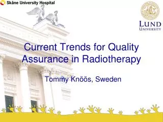
Automated Image Analysis Software for Quality Assurance of a Radiotherapy CT Simulator. Andrew J Reilly. Imaging Physicist Oncology Physics Edinburgh Cancer Centre Western General Hospital EDINBURGH EH4 2XU. Phone: 0131 537 1161 Fax: 0131 537 1092 E-Mail: andrew.reilly@luht.scot.nhs.uk

E N D
Automated Image Analysis Software for Quality Assurance of a Radiotherapy CT Simulator Andrew J Reilly Imaging Physicist Oncology Physics Edinburgh Cancer Centre Western General Hospital EDINBURGH EH4 2XU Phone: 0131 537 1161 Fax: 0131 537 1092 E-Mail: andrew.reilly@luht.scot.nhs.uk Web: http://www.oncphys.ed.ac.uk
Overview • Radiotherapy imaging • RT Imaging QA: problems and solution • Describe features of auto analysis software • Demonstrate application to CT-Sim and Sim-CT • Outline experience to date
Integrated System Imaging Modalities for RT • Common • Simulator (fluoroscopy) • CT-simulator • Digitally Reconstructed Radiographs (DRRs) • Simulator-CT (single slice and cone-beam) • Electronic Portal Imaging Devices (EPIDs) • ‘Emerging’ • Ultrasound • MRI • PET • On treatment cone-beam CT and kV radiography
RT Imaging QA: Essential Tests • Geometric Accuracy in 3D • In and out of image plane (pixel size, couch travel) • Mechanical alignments • Laser alignment • Image quality • Sufficient for purpose? • Consistent over time • Accurate physical information • CT number / HU calibration -> electron density • Testing of overall system • Geometrical co-registration • Transfer of image data
The Problems… • Different tests are specified for different modalities • Range of ‘equivalent’ test objects • Most tests are only semi-quantitative • Operator dependency • Frequent (daily/fortnightly) comprehensive testing is required BUT most tests are time-consuming • Some imaging equipment performs too well! • Difficult to test integrated system.
The Solution… • Develop single, uniform approach for all RT imaging modalities • + display devices, film processors, etc. • Robust, fully objective and quantitative • Analysis performed by computer • Results automatically stored in database for trend analysis, etc.
The Approach 1. Develop Appropriate Phantom 2. Acquire Image of Phantom Signal Signal s1 s1 s2 s2 SNRin = s1 / s2 SNRout = s1 / s2
Determining the DQE Modulation Transfer Function (Phantom) Dose and acquisition setting dependent. Noise Power Spectrum (Phantom)
Varian Ximatron EX Sim-CT Additional Collimators
Varian Performance Phantom A A WATER 1 2 INNERBONE LUNG L R R L MTF 3 q CORT BONE AIR P P
Varian Uniformity Phantoms 34 cm 44 cm Polyurethane Casting HU -580
Geometry: Phantom Alignment • Detect phantom edge • Threshold at –580 • Trace edges and choose largest contour • Calculate COM • Compare against CT zero position
Geometry: Pixel Size • Measure distance between holes • Use centre of phantom and expected pixel size to identify ‘seek area’ • Local minimum is centre of hole
Hounsfield Unit Calibration Baseline Values Measured During Commissioning
Modulation Transfer Function • Calculate from impulse object Finite size (DSF)
Calculation from Impulse Object Object Spread Function (From ALL pixels in ROI)
Uniformity Phantom Analysis • Define Useful FOV (UFOV) as 90% FOV • Calculate:
Sim-CT Urethane Norm Air Norm Uniformity Profiles CT Sim: 50 cm FOV
Noise Power Spectrum • Region of Interest from Uniformity Phantom • Remove DC component (subtract mean value) • Perform 2D FFT • Separation of stochastic noise
NPS Example • 100 images of Uniformity Phantom, 50 cm FOV
Reference: Milickovic et al, Physics in Medicine and Biology (2000) 45:10;2787-2800 Projected back to isocentre Production of DRRs • Ray trace from virtual source of x-rays through stack of CT slices and model attenuation of beam. X-ray source SAD 100 cm isocentre Imaging Plane
DRR Production Example 3D array of voxels CT Slices DRR
Experience & Conclusions • New approach appears complicated, but… • Significantly faster than previous methods • More robust, fully objective and quantitative • Greater confidence in results • New ability to follow trends • Need to finalise DRR phantom • Expand to include other RT imaging modalities