Computer assisted part programming (APT, A utomatically P rogrammed T ool)
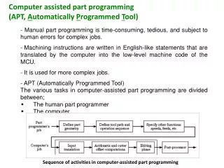
Computer assisted part programming (APT, A utomatically P rogrammed T ool). - Manual part programming is time-consuming, tedious, and subject to human errors for complex jobs.

Computer assisted part programming (APT, A utomatically P rogrammed T ool)
E N D
Presentation Transcript
Computer assisted part programming • (APT, Automatically Programmed Tool) • - Manual part programming is time-consuming, tedious, and subject to human errors for complex jobs. • Machining instructions are written in English-like statements that are translated by the computer into the low-level machine code of the MCU. • It is used for more complex jobs. • - APT (Automatically Programmed Tool) • The various tasks in computer-assisted part programming are divided between; • The human part programmer • The computer. Sequence of activities in computer-assisted part programming
Part Programmer's Job • Two main tasks of the programmer: • 1- Define the part geometry • 2- Specify the tool path and Operation Sequence • 1- Define the part geometry • Underlying assumption: no matter how complex the part geometry, it is composed of basic geometric elements and mathematically defined surfaces • Geometry elements are sometimes defined only for use in specifying tool path • Examples of part geometry definitions: • P4 = POINT/35, 90,0 • L1 = LINE/P1, P2 • C1 = CIRCLE/CENTER, P8, RADIUS, 30.0
2- Specify the tool path and Operation Sequence • Tool path consists of a sequence of points or connected line and arc segments, using previously defined geometry elements • Point-to-Point command: • GOTO/P0 • Continuous path command: • GOLFT/L2, TANTO, C1 Other Functions in Computer-Assisted Part Programming • Specifying cutting speeds and feed rates • Designating cutter size (for tool offset calculations) • Specifying tolerances in circular interpolation • Naming the program • Identifying the machine tool
Cutter Offset Cutter path must be offset from actual part outline by a distance equal to the cutter radius Computer Tasks in Computer-Assisted Part Programming • Input translation – converts the coded instructions in the part program into computer-usable form • Arithmetic and cutter offset computations – performs the mathematical computations to define the part surface and generate the tool path, including cutter offset compensation (CLFILE) • Editing – provides readable data on cutter locations and machine tool operating commands (CLDATA) • Postprocessing – converts CLDATA into low-level code that can be interpreted by the MCU
There are four basic types of statements in the APT language: • 1.Geometry statements, also called definition statements; are used to define the geometry elements that comprise the part. • Motion commands; are used to specify the tool path. • Postprocessor statements; control the machine tool operation, for example, to specify speeds and feeds, set tolerance values for circular interpolation, and actuate other capabilities of the machine tool. • Auxiliary statements; a group of miscellaneous statements used to name the part program, insert comments in the program and accomplish similar functions. - APT vocabulary words consist of six or fewer characters. The characters are almost always letters of the alphabet.
Geometry statements The points, lines, and surfaces must be defined in the program prior to specifying the motion statements. The general form of an APT geometry statement is the following: SYMBOL = GEOMETRY TYPE/descriptive data as an example; P1 = POINT/20.0, 40.0, 60.0 A symbol can be nay combination of six or fewer alphabetical and numerical characters, at least one of which must be alphabetical. Also the symbol cannot be an APT vocabulary word. Some examples are presented in the following Table: major words minor words
Points: Specification of a point can be accomplished by the following: • Designating its x-, y-, and z-coordinates; • P1 = POINT/15.0, 10.0, 25.0 • 2) As the intersection of two intersecting lines; • P2 = POINT/INTOF, L1, L2 • L1 and L2 are two previously defined lines. Lines: A line in APT is considered to be of infinite length in both directions. Specification of a line can be accomplished by the following: 1) Two points through which it passes; L1 = LINE/P3, P4 P3 and P4 are two previously defined points. 2) Passes through point (P5) and parallel to another line (L3) that has been previously defined; L2 = LINE/P5, PARLEL, L3
Planes: In APT, a plane extends indefinitely. A plane can be defined by the following: 1) Three points through which it passes; PL1 = PLANE/P1, P2, P3 P1, P2 and P3 must be non-collinear. 2) Passes through point (P2) and parallel to another plane (PL1) that has been previously defined; PL2 = PLANE/P2, PARLEL, PL1 Circles: In APT, a circle is considered to be a cylindrical surface that is perpendicular to the x-y plane and extends to infinity in the z-direction. A circle can be defined by the following: 1) Its center and radius; C1 = CIRCLE/CENTER, P1, RADIUS, 25.0 2) Three points through which it passes; C2 = CIRCLE/P4, P5, P6 The three points must not be collinear.
Motion Commands All APT motion statements follow a common format, just as geometry statements have their own format. The general form of an APT motion command is: MOTION COMMAND/descriptive data as an example; GOTO/P1 - At the beginning of the sequence of motion statements, the tool must be given a starting point. This is likely to be the target point, the location where the operator has positioned the tool at the start of the job. The part programmer keys into this starting position with the following statement: FROM/PTARG Where FROM is an APT vocabulary word indicating that this is the initial point from which all others will be referenced; and PTARG is the symbol assigned to the starting point. Another way to make this statement is the following: FROM/-20.0, -20.0, 0 - The FROM statement occurs only at the start of the motion sequence.
It is appropriate to distinguish between point-to-point motions and contouring motions. Point-to-point motions There are two commands; GOTO and GODLTA. * The GOTO statement instructs the tool to go to a particular point location specified in the descriptive data. Two examples are: GOTO/P2 GOTO/25.0, 40.0, 0 * The GODLTA command specifies an incremental move for the tool. To illustrate, the following statement instruct the tool to move from its present position by a distance of 50 mm in x-direction, 120 mm in y-direction, and 40 mm in z-direction; GODLTA/50.0, 120.0, 40.0 * The GODLTA statement is useful in drilling and related machining operations. The tool can be directed to go to a given hole location; then the GODLTA command can be used to drill the hole, as in the following sequence; GOTO/P2 GODLTA/0, 0, -50.0 GODLTA/0, 0, 50.0
Contouring motions • These are more complicated than PTP commands are because the tool’s position must be continuously controlled throughout the move. • The tool is directed along two intersecting surfaces until it reaches a third surface, as shown in the following Figure; • Drive surface; this is the surface that guides the side of the cutter. It is pictured as a plane in our Figure. • Part surface; this is the surface, again pictured as a plane, on which the bottomor nose of the tool is guided. • Check surface; this is the surface that stops the forward motion of the tool in the execution of the current command. One might say that this surface “checks” the advance of the tool.
Initialization of APT contouring motion sequence: With reference to the Figure, the sequence takes the following form: FROM/PTARG GO/TO, PL1, TO, PL2, TO, PL3 - The three surfaces included in the GO statement must be specified in the order; (1) drive surface, (2) part surface, and (3) check surface. - Note that GO/TO is not the same as the GOTO command. GOTO is used only for PTP motions. The GO/ command is used to initialize a sequence of contouring motions and may take alternative forms such as GO/ON, GO/TO, or GO/PAST.
It is not necessary to redefine the part surface in every motion command after it has been initially defined as long as it remains the same in subsequent commands; GORGT/PL3, PAST, PL4 * In engineering drawing, the sides of the part appear as lines, although they are three-dimensional surfaces on the physical part. In cases like this, it is more convenient for the programmer to define the part profile in terms of lines and circlesrather than planes and cylinders. L4 L3 L1 * APT language system allows this because in APT, lines are treated as planes and circles are treated as cylinders, which are both perpendicular to the x-y plane. Hence, the planes around the part outline can be replacedby lines (L1, L3, and L4). The commands can be replaced by the following; FROM/PTARG GO/TO, L1, TO, PL2, TO, L3 GORGT/L3, PAST, L4 - Plane PL2 has not been converted to a line. As the “part surface” in the motion statement, it must maintain its status as a plane parallel to the x- and y-axes.
Postprocessor and Auxiliary statements Postprocessor statements control the operation of the machine tool and play a supporting role in generating the tool path. Such statements are used to define cutter size, specify speeds and feeds, turn coolant flow on and off, and control other features of the m/c tool. The general form of the postprocessor statement is: POSTPROCESSOR COMMAND/descriptive data In some commands, the descriptive data is omitted. Some examples of the postprocessor statements are the following:
Auxiliary statements are used to identify the part program, specify which postprocessor to use, insert remarks into the program, and so on. Some examples are following:
Another APT statements are found in the Appendix (ref. Groover, p. 196 – 209). Write the APT program to: Drill the shown holes (Example 1). Mill the shown shape (Example 2). y Solution of Example 1: x
PARTNO SAMPLE PART DRILLING OPERATION MACHIN/DRILL,01 CLPRNT UNITS/MM REMARK Part geometry, Points are defined 10 mm above part surface. PTARG = POINT/0, -50.0, 10.0 P5 = POINT/70.0, 30.0, 10.0 P6 = POINT/120.0, 30.0, 10.0 P7 = POINT/70.0, 60.0, 10.0 REMARK Drill bit motion statements. FROM/PTARG RAPID GOTO/P5 SPINDL/1000, CLW FEEDRAT/0.05, IPR GODLTA/0, 0, -25.0 GODLTA/0, 0, 25.0 RAPID GOTO/P6 SPINDL/1000, CLW FEEDRAT/0.05, IPR GODLTA/0, 0, -25.0 GODLTA/0, 0, 25.0 RAPID GOTO/P7 SPINDL/1000, CLW FEEDRAT/0.05, IPR GODLTA/0, 0, -25.0 GODLTA/0, 0, 25.0 RAPID GOTO/PTARG SPINDL/OFF FINI
Solution of Example 2: Feed = 50 mm/min., Speed = 1000 rev/min., Cutter diam. = 20 mm. PARTNO SAMPLE PART MILLING OPERATION MACHIN/MILLING,02 CLPRNT UNITS/MM CUTTER/20.0 REMARK Part geometry, Points and Lines are defined 25 mm below part top surface. PTARG = POINT/0, -50.0, 10.0 P1 = POINT/0, 0, -25.0 P2 = POINT/160.0, 0, -25.0 P3 = POINT/160.0, 60.0, -25.0 P4 = POINT/35.0, 90.0, -25.0 P8 = POINT/130.0, 60.0, -25.0 L1 = LINE/P1, P2 L2 = LINE/P2, P3 C1 = CIRCLE/CENTER, P8, RADIUS, 30.0
L3 = LINE/P4, LEFT, TANTO, C1 L4 = LINE/P4, P1 PL1 = PLANE/P1, P2, P4 REMARK Milling cutter motion statements. FROM/PTARG SPINDL/1000, CLW FEEDRAT/50, IPM GO/TO, L1, TO, PL1, ON, L4 GORGT/L1, PAST, L2 GOLFT/L2, TANTO, C1 GOFWD/C1, PAST, L3 GOFWD/L3, PAST, L4 GOLFT/L4, PAST, L1 RAPID GOTO/PTARG SPINDL/OFF FINI